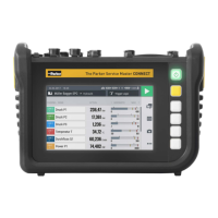
ENGLISH
3.3 Connections
The figure indicates the connection ports on the device:
98765
4
32
1
Fig.3 Connections
Pos. Designation Description
1 Power connection (24V
DC
) For connection of the power adapt-
er
2 CAN bus (CAN X) To connect the CAN bus
sensors
3 CAN bus (CAN Y) To connect the CAN bus
sensors
4 D-IN/D-OUT F1/F2 To connect sensors
5 SIM card slot Slot for a SIM card
6 USB port (device) To connect a PC
7 USB port (Host 1) To connect a mass storage
device
8 USB port (Host 2) To connect a mass storage
device
9 LAN connection port To connect a network cable
More information on the sensor connection ports is available
in the following chapters.
INFORMATION
Do not connect the device via the LAN and USB ports simultaneously
when transmitting data to SensoWin. This will prevent any distur-
bance.
159
The Parker Service Master CONNECT V1.0/04/20
Design and Function
 Loading...