131
ACU-TROL
®
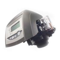
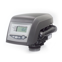
AK110 Chemical Controller Installation and User's Guide
DWG. # PART # DESCRIPTION
1 715000150 Enclosure, Lid, w/overlay and hardware
2 724000260 PCB, Control Board, w/display and hardware
3 724000010 PCB, Sensor, pH/orp/temp w/hardware
4 724000020 PCB, Sensor, pH/temp/AKColor, w/hardware
NS 724000280 PCB, Module, Real Time Clock, w/hardware
NS 724000290 PCB, Module, RS232 adapter, w/hardware (optional)
5 724000050 PCB, Module, Relay, w/hardware
6 724000300 PCB, Relay board, w/hardware (3)
7 714000270 Switch,ON/Off,w/jumpers,wires,powercord,strainrelief
8 714000210 Cable, Ribbon
9 714000280 Enclosure, Top Half, Complete
10 714000290 Enclosure, Bottom Half, Complete
NS 714000170 Fuse, 1 AMP
NS 714000180 Fuse, 5 AMP
11 754001910 Mounting Feet (4)
12 714000300 Strain Relief (2 small , 3 large)
13 744000270 Kit, pH Sensor, w/BNC Cable
14 744000340 Kit, ORP Sensor, w/BNC Cable
NS 754000320 Parts Bag, Flow Cell, Complete
15 754000360 Filter, Flow Cell
16 754002010 Ball Valve (2)
17 754002000 Fitting,Jaco(2)
18 754000440 Switch,Flow,w/10’cable
19 754001990 Top, Flow Cell, w/ flow switch and nylon plugs
20 754000340 ClearJellyJar,FlowCell,w/o-ring
21 754000350 O-ring,ClearJellyJar,FlowCell
22 754001980 Kit, Sample Port
AK110 Pool and Spa Chemical Controller Illustrated Parts List

 Loading...