48
Shortcut Keys
AK110 Main Status Screen Navigation (2 of 2)
Acu-Trol, SN123456
Swimming Pool
Automatic Controller
AK110E7, 07/22/08
Version Control Screen
pH > 7.67-OFF 7.50s
ORP 490 -OFF 700s
_____
69.0f SW1OFFSW2OFF
Main Status, cursor anywhere
>Name:Main Pool
System
Programming
Service
Data ( 8:441 )
Communications
Security Setup
Wizards
Serial # 123456
Configuration Menu Screen
System Information Screen
TotalON 12:34hrs
MemoryWR 1
Watchdog 0
0 0 0
"Any"
Key
6
Back
4
Back
pH > 7.67-OFF 7.50s
ORP 490 -OFF 700s
_____
69.0f SW1OFFSW2OFF
Main Status, cursor anywhere Modem Diagnostics Screen
+++ATH OK AT&F&C1&D1
&K0S8=4 OK _
Pager 0PgD: 0
Sts 0 6789 0
pH > 7.67-OFF 7.50s
ORP 490 -OFF 700s
_____
69.0f SW1OFFSW2OFF
Main Status, cursor anywhere Diagnostics Password Screen
Enter Password
Enter:
v-Cancel
pH > 7.67-OFF 7.50s
ORP 490 -OFF 700s
_____
69.0f SW1OFFSW2OFF
Main Status, cursor on value Reset Calibration Screen
-Confirm Changes
-Reset current calib
ration?
NO:7 9:Yes
0
9
7
or
pH > 7.67-OFF 7.50s
ORP 490 -OFF 700s
_____
69.0f SW1OFFSW2OFF
Main Status, cursor at top row
9
"Any"
Key
pH > 7.67-OFF 7.50s
ORP 490 -OFF 700s
_____
69.0f SW1OFFSW2OFF
Main Status, cursor anywhere
Back
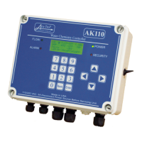
A numer of screens may be quickly accessed direcly through the Main Status
Screen. The primary purpose of these screens is to conveniently provide system
identification, configuration and diagnostic information to the user or to service
personnel.
The System Information Screen
displays unit information such as
total unit on-time and internal
system counters.
Press the [9] key to go to the
System Information Screen.
Press "any" key to return to the
Main Status Screen.
Press the [6] key to go to the
Modem Diagnostics Screen.
Press the [Back] key to return to the
Main Status Screen.
An optional modem must be
installed in the AK110 in order for
the Modem Diagnostics Screen to
display pertinent data.
Press the [4] key to go to the
Diagnostics Password Screen.
Press the [Back] key to return to the
Main Status Screen.
The Diagnostics Password Screen
is intended for use by Acu-Trol
factory and authorized product
support personnel only.
Press the up arrow key to go to the
Version Control Screen.
Press "any" key to return to the
Main Status Screen.
The Version Control Screen
displays identifying unit information
including the serial number and the
installed firmware revision.
Press the [9] key to reset the
selected calibration offset to
zero or the [7] key to cancel.
Move the cursor to a sensor
measurement value and
press the [0] key to go to the
Reset Calibration Screen.
Press the [Back] key to go to the
Configuration Menu Screen.
Press the [Back] key once again to
return to the Main Status Screen.
Flow Switch #2
SW2 K =
> 0.0 pul/g
Clear
Flow Switch 2 Setup, K-Factor
Flow Switch #2
SW2 K = 8.5 pul/g
g/m = 35
Total = 256
>Clear
Flow Switch 2 Setup, Clear Counter
Enter new value
Current: 0.0
0.0
v-Cancel ^
Flow Switch K-Factor Screen
Use the keypad to enter the K-factor
for the installed flow meter.
Press the [Enter] key to confirm or
the down arrow key to cancel.
Enter
Enter
Switch 2 Setup, Clear Counter
Flow Switch #2
SW2 K = 8.5 pul/g
g/m = 35
Total = 0
>Clear
Flow Switch #2
SW2 K = 3.6 pul/l
l/m = 83
Total = 372
>Clear
Flow Switch 2 Setup, Metric Units
Digital Flow Meter Setup
If the AK110 is configured to display
metric units of measurement, the
flow sensor values will be displayed
in liters rather than gallons.
Main Status, Cursor at Flow Switch 2
pH 7.67-OFF 7.50s
ORP 490 –OFF 700s
_____
69.0f SW1OFF>W2OFF
The unit "g/m" represents the
measured flow rate. "Total" is the
accumulated volume, as calculated
by the flow rate and the K-factor.
Press the [Enter] key to reset the
accumulated volume counter to
zero.
The two flow switch inputs are, in the default configuration, set up as simple on/
off switches. One or both of these flow switch inputs may be configured to
operate with a digital flow meter to measure the flow rate through a pipe.
Assigning a K-factor of "0.0" to a flow switch allows it to operate as a simple on/
off flow switch. As Flow Switch 1 functions as the default flow switch for relay
control, it is recommended that it remain configured as a simple on/off flow
switch.
To set up a flow switch input to operate with a digital flow meter, enter in the
sensor K-factor. The flow rate is displayed on-screen as gallons per minute (g/m)
or as liters per minute (l/m). Furthermore, the accumulated volume is tallied and
displayed (in gallons or in liters) as the "Total" volume.
In this example, Flow Switch 2 is configured to operate with a digital flow meter.
EnterBack
Main Status, Switch 2 Flow Rate
pH > 7.67-OFF 7.50s
ORP 490 –OFF 700s
_____
69.0f SW1ON
FM 35
Once Flow Switch 2 has been
configured to operate with a digital
flow sensor, the measured flow rate
is displaed in the "SW2" position.
pH > 7.67-OFF 7.50s
PPM 2.65-OFF 2.00s
_____
69.0f SW1OFFSW2OFF
Main Status, cursor on the far left
Back
AKColor™ Status Screen
FREE= 2.65 75/240
MixingDPD
lvl= 90%
CLRv= 3.48 v= 1.98
Press the left arrow key to go to the
AKColor Status Screen.
Press the [Back] key to return to
the Main Status Screen.
An optional colorimetric interface
sensor card must be installed in the
AK110 in order for the AKColor™
Status Screen to be accessable.
AK110 Main Status Screen Navigation, Rev 3 21 Aug 2008
 Loading...
