11
Instructions for Assembly and Use – Standard Configuration
CB 160 Climbing Formwork
A1 Assembly of the CB 160 platforms
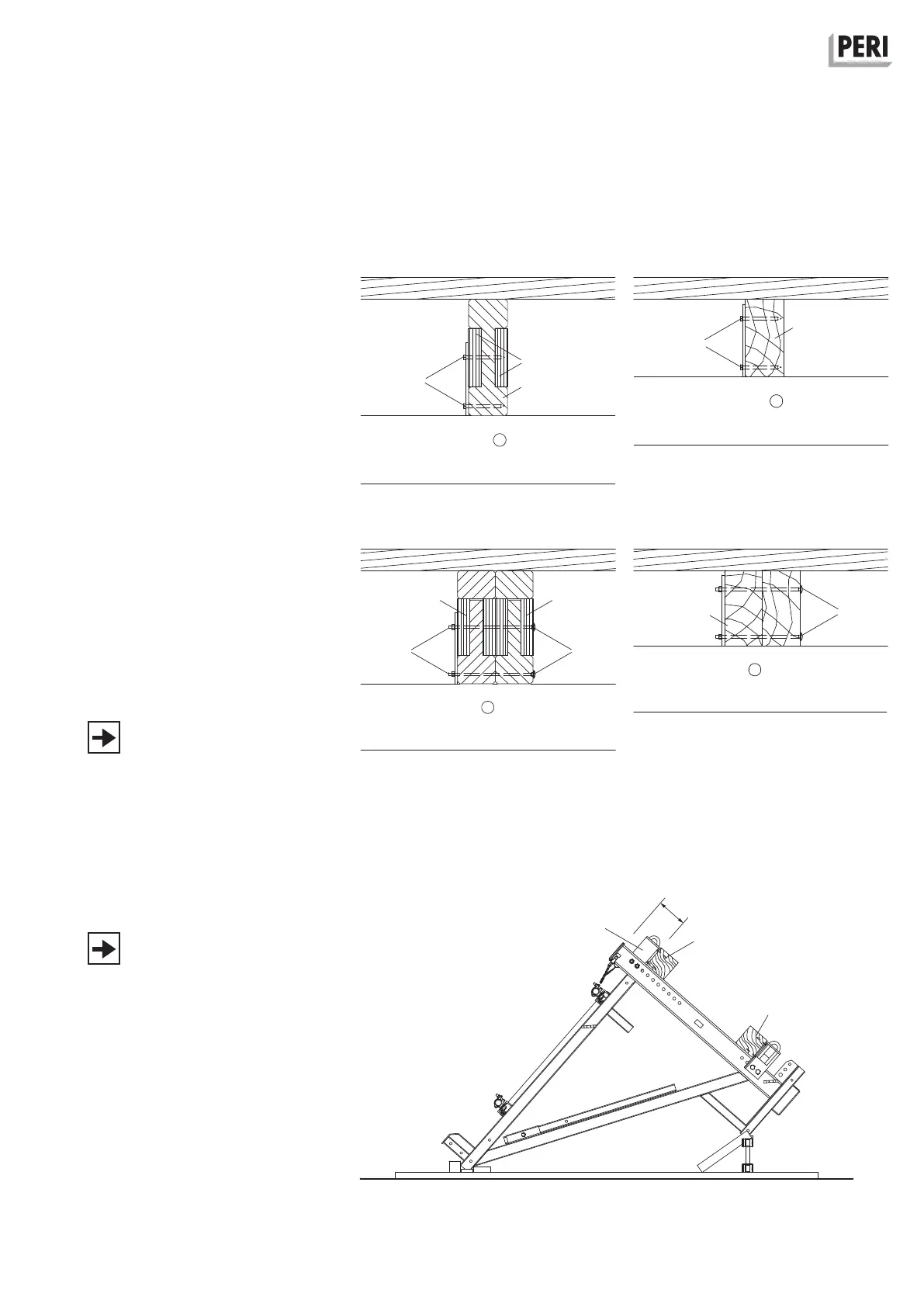
Single girder position
– plywood or 3-ply board (13.2)
– hex. wood screw 6 x 80 (13.3)
– timber 8/16 (13.6)
– GT 24 lattice girder (13.7)
(Fig. A1.09 + A1.10)
Double girder position
– plywood or 3-ply board (13.2)
– hex. wood screw 6 x 80 (13.3)
– timber 8 x 16 (2x) or 16 x 16 (1x)
(13.6)
– F. H.Bolt M6 x 180 (13.4)
– GT 24 lattice girder (13.7)
(Fig. A1.11 + A1.12)
These drawings conform to Appendix
K15 of the type test issued by the State
Structural Inspectorate, Düsseldorf, test
certificate no. P31 - 95/91 and may only
be used in accordance with the afore-
mentioned type test.
Assembly as working scaffold
For operating the securing bolts from
above, a spacing of x ≥ 23 cm is re-
quired.
1. Bolt on two Platform Connections
CB 160 (1.4) per bracket.
(Fig. A1.13)
2. For supporting the decking, fix tim-
bers h = 16 cm (13.6) with hex. wood
screws 6 x 80 (13.3).
Fig. A1.09
Fig. A1.11
Fig. A1.10
Fig. A1.12
Fig. A1.13
13.7
13.6
13.213.2
1.4
13.3, 13.6
13.3, 13.6
x ≥ 23 cm
13.6
13.3 13.4
16
13.3
13.2
13.3
13.4
GT 24 Girder Timber
 Loading...


