60
Klettertraverse RCS 10 t
Art.-Nr. 112986
Ausgabe 04/2008
Betriebsanleitung
Instructions for Assembly and Use – Standard Configuration
CB 160 Climbing Formwork
C1 Planning and work preparation
Moving the units
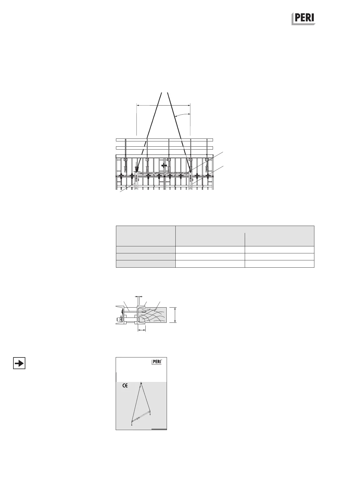
Installation of compression brace
In order to prevent the strongbacks
from being pulled out of line during the
lifting process due to the redirection of
forces, clamp a suitable piece of timber
(4.10) as a compression brace between
the top ends of the strongbacks (4).
(Fig. C1.14)
Dimensions of the compression brace
see Table 5.
Top viewThe timber ends (4.10) are to be adapt-
ed to the U120 profile of the strongback
(4) through chamfering and notching.
For fixing with wood screws 8 x 160
and washers (4.11), use the drilled
holes in the strongback web.
(Fig. C1.15)
If no compression braces are used be-
tween the strongbacks or strongly un-
balanced platforms are to be moved,
we recommend the use of the Lifting
Beam RCS 10 t, Item no. 112986.
Instructions for Assembly and Use:
see Fig. C1.16.
b
5
≤ 45°
L
Fig. C1.15
Fig. C1.16
Fig. C1.14
4.11
4 4.10
4.10
4
4
Table 5
Permissible spacing for the Strongback CB
1 x 45°
_ ≤ 30° _ = 45°
10 x 10 4.30 3.80
12 x 12 5.20 5.20
14 x 14 6.00 6.00
Dimensions of the
compression brace
b x d [cm]
Crane sling angle Crane sling angle
Permissible spacing for the Strongback CB L [m]