56
V
1
Instructions for Assembly and Use – Standard Configuration
CB 240 Climbing Formwork
C1 Planning and work preparation
Connecting VARIO GT 24
formwork
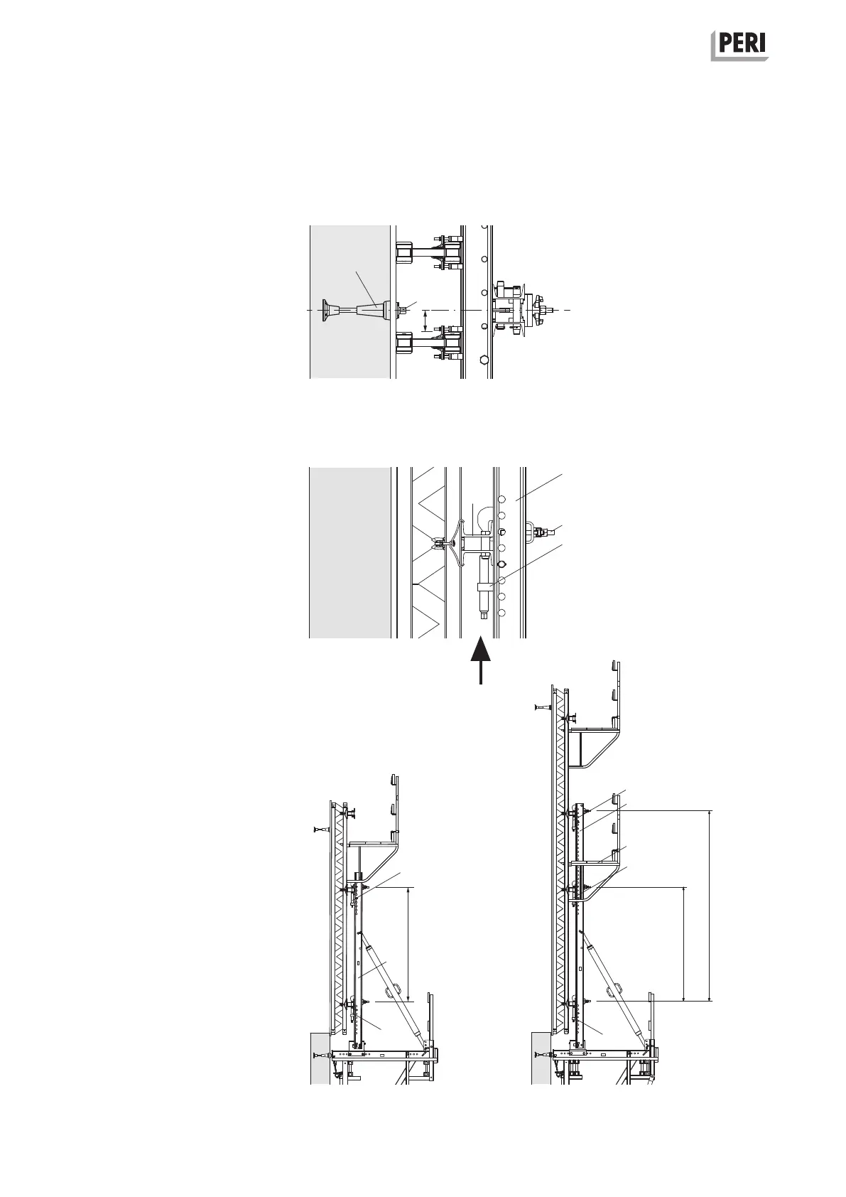
Mounting the leading anchor
During formwork design, attention
must be paid that there is sufficient
spacing between the bracket axis and
the GT 24 formwork girder.
Otherwise, mounting the Leading An-
chor (5) with the Anchor Positioning
Stud M24 (5.9) is not possible.
(Fig. C1.05)
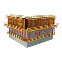
Height adjusting units
Depending on the weight of the form-
work, the number of Height Adjusting
Units (4.3) is to be determined for each
strongback.
(Fig. C1.06)
perm. V
1
= 12.8 kN
Fix all walers (10.4) in the area of the
strongback (4) with waler fixations (4.4).
Strongback CB 270 (4.1)
The top height adjusting unit is only
mountable with standard waler spac-
ings of 1.78 m or 2.07 m.
(Fig. C1.07a)
Strongback CB 380 (4.2)
The top height adjusting units are only
mountable on walers in standard spac-
ings from 1.78 m to 3.26 m from the
lowest-positioned waler.
(Fig. C1.07b)
Fig. C1.05
Fig. C1.07a Fig. C1.07b
1.78 m
2.07 m
1.78 m
2.96 m
4.1
4.3
4.4
5
5.9
3cm>
Fig. C1.06
4
10.4
4.3
4.3
4.2
4.3
4.3
4.4
4.3