12
24
Instructions for Assembly and Use – Standard Configuration
CB 160 Climbing Formwork
A1 Assembly of the CB 160 platforms
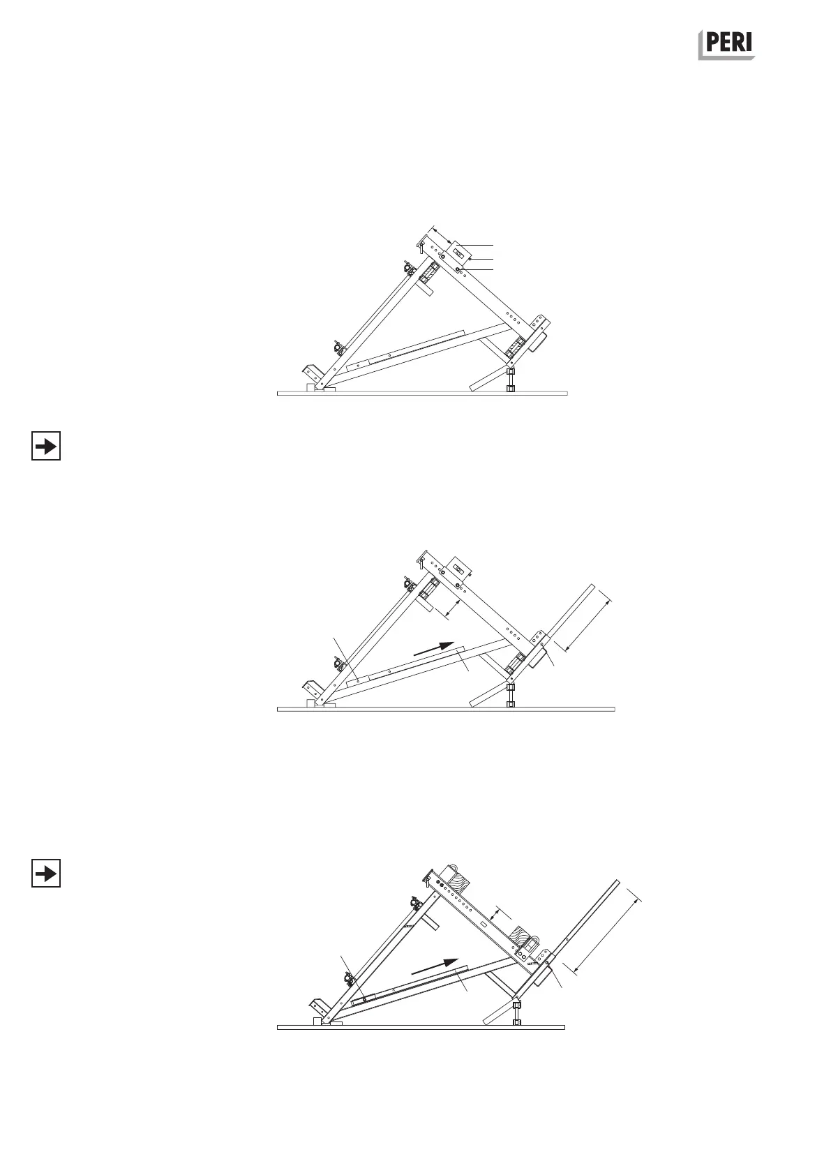
Assembly of
Adjusting Unit CB 160
Assembly
When using TRIO or VARIO GT 24, the
Adjusting Unit CB 160 (2) has to be
assembled with Hex. Bolts M20 x 150
(2.3), SW 30. Bolts M20 x 150 (2.3),
SW30.
The Adjusting Bolt (2.2) points to the
guardrail side.
(Fig. A1.14)
Another position may be predefined in
the plan.
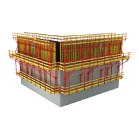
Assembly of
Guardrail Post CB
Assembly
1. Loosen bolt (1.6) and take out SW 24,
and guardrail post (1.2).
2. Insert guardrail post in the holder.
3. Fix with Bolt (1.6) and self-securing
nut.
4. Proceed in the same way with the
second guardrail post.
(Fig. A1.15 or A1.16).
Arrangement of the girder below: top
hole (a) in the guardrail post.
(Fig. A1.15)
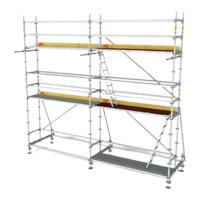
Arrangement of the girder above: bot-
tom hole (b) in the guardrail post
(Fig. A1.16)
Fig. A1.14
Fig. A1.15
Fig. A1.16
SW 30
2
2.2
2.3
1.2
1.6
1.6 (a)
1.6 (b)
16
27
0.705 m
1.025 m
1.2
1.6