36 Instructions for Assembly and Use – Standard Configuration
CB 160 Climbing Formwork
B2 Assembly of formwork elements
VARIO GT 24 element
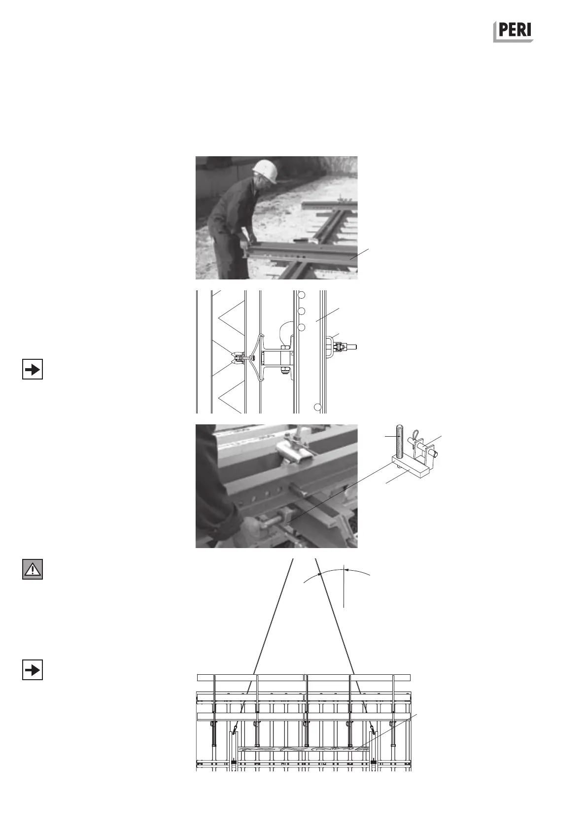
Assembly of Strongback CB
on the VARIO GT 24 element
1. Lay Strongback CB 270 or CB 380 (4)
on the steel waler of the VARIO GT 24
formwork according to the bracket
spacing. Bottom projecting length:
see Planning or C1. (Fig B2.01)
2. Mount Waler Fixation U 100 – U120
(4.4) and secure in position by tight-
ening the quick jack nut. (Fig. B2.02)
3. Fix Height Adjusting Unit (4.3) with
bolts Ø 25 x 180 (4.6) and cotter pin
to the Strongback CB. (Fig. B2.03)
4. Turn height adjusting unit spindle
(4.8) against the formwork waler.
The Waler Fixation U100 - U120 can be
attached to the SRZ steel walers U100
and U120.
Fig. B2.01
In order to prevent the strongbacks
from being pulled out of position at
any time, a piece of timber (4.10) has
to be clamped between the top ends
of the strongbacks, see C1 Moving
(Fig. B2.04)
Alternatively, use Lifting Beam RCS 10 t
(Item no. 112986) for moving.
Fig. B2.02
Fig. B2.03
4
4.8
4
4.4
4.3
4.6
≤ 45°
Fig. B2.04
4.10