61
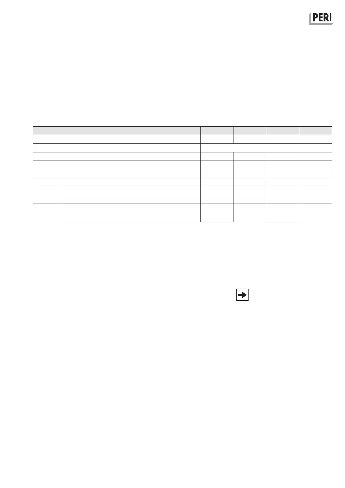
1.5 – 3.0 2.0 – 3.0 3.3 – 4.9 3.8 – 5.4
3.65 4.15 5.45 5.95
051430 1111
051420 1111
051410 1122
051450 1112
104132 ––1–
109105 1111
103718 2–2–
070711 1* –** 1* –**
Instructions for Assembly and Use – Standard Configuration
CB 160 Climbing Formwork
C1 Planning and work preparation
Ladder Access
Table 6
Parts list for ladder access
**
The ladders are attached to the top end of the sliding hatch cover.
The bottom ladder is attached using the ladder hook, and with the ladder base on timber at the lower end.
*
Screw ladder base tightly on decking of the finishing platform.
Working platform - finishing platform spacing [m]
Item no.
Sliding Hatch
Ladder 220/6
Ladder 180/6, galv.
Ladder Safety Cage 150, galv.
Concreting height [m]
Description
Parts List
Ladder Safety Cage 75, galv.
Ladder Base 30, galv.
Timber 10 x 10, L = 60 cm for assembly of Ladder Base 30
Ladder Hook, galv.
Assembly Drawings
At least the following points should
be featured in the assembly drawings:
– bracket spacing and bracing
– dimensions of the working and finish-
ing platform
– dimensions, arrangement and num-
ber of concreting and intermediate
platforms
– erection of girders and guardrails
– layout of end guardrail posts
– layout of lateral guardrails
– position of access ladders
– material requirements (parts list)
Drawings and plans
General Arrangement Drawings
At least the following points should
be featured in the general arrange-
ment drawings:
– position of the climbing anchor in the
plan view and sectional view
– which scaffolding platform is used on
which part of the building
– associated formwork and finishing
platform
– installation of wind bracing
– distance of finishing platform to the
working platform
– formwork and strongback connection
points
– timber brace position between the
strongbacks
– reference values for retraction dis-
tance during moving (see Table 1)
– possible special measures in case of
irregular concreting heights
– details of modifications
– material requirements (parts list)
Appropriate, easy-to-read as well as
sufficient drawings in both number and
format are to be made available to the
site management. The drawings are to
be created clearly and professionally in
the language of the country where con-
struction is taking place.
We recommend including a plan view
and sectional view of the scaffold as
well as an overview plan for positioning
purposes.
We recommend including a plan view
and a top view of the platform.