10 Instructions for Assembly and Use – Standard Configuration
CB 160 Climbing Formwork
A1 Assembly of the CB 160 platforms
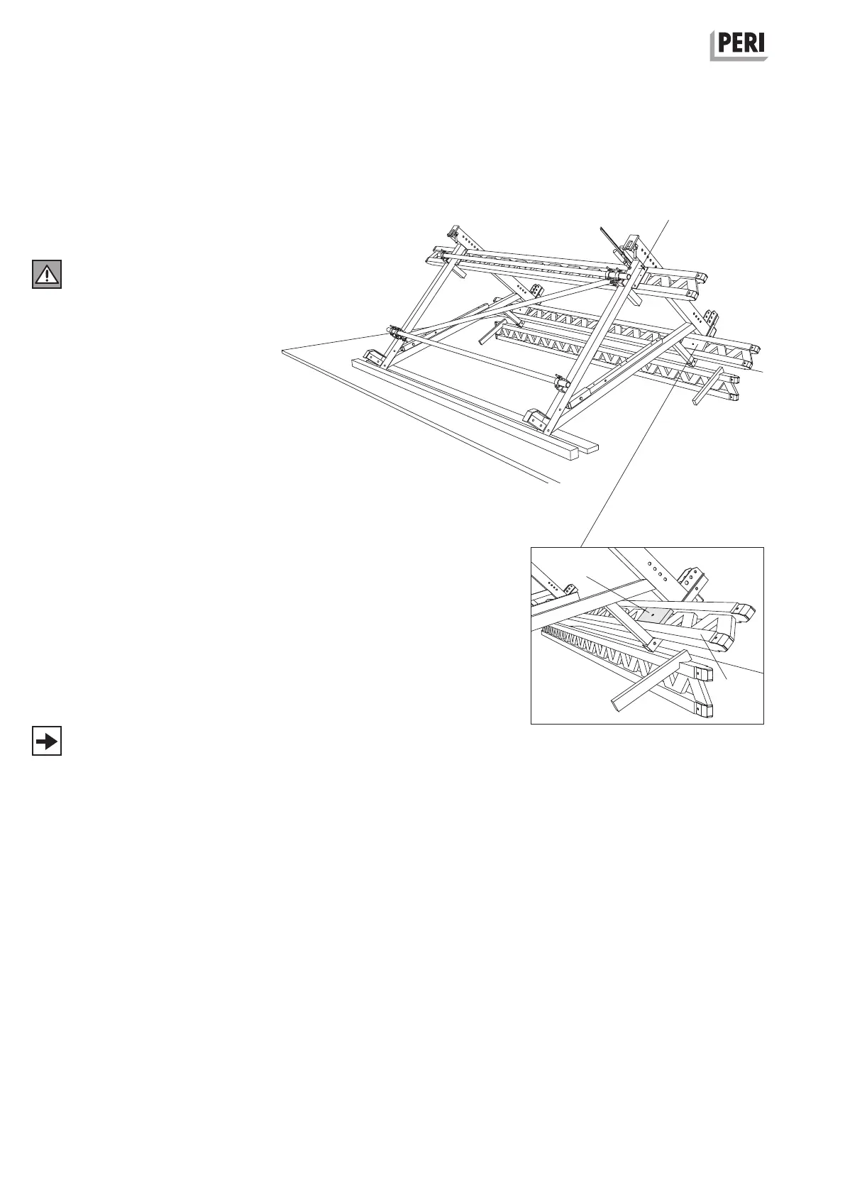
Assembly of girders
When using PERI GT 24 girders,
strengthen them on both sides in the
area of the brackets with plywood
strips (13.2). (Fig. A1.08)
In order to avoid the risk of lifting in
the case of large cantilevers, timber
blocks must be placed on the oppo-
site side in-between the bracket
cross-beams and girders. Fix to the
girders by means of wood screws.
Dimensions: thickness/width/height
27 x 120 x 300 mm
Fixing: Torx TSS 6 x 60
Assembly
1. Fix girder (13.1) by means of screw
clamps.
2. Fix diagonals to the fixing plates
using two hex. wood screws 6 x 80
(13.3) in each case.
(Fig. A1.08)
Alternatively:
F. H. Bolts M6 x 100, washer or for
double girders M6 x 180 (13.4).
(Fig. A1.08a)
– If no girders have been included in
the planning, these can be deter-
mined from C1 Platform deckings.
– Pre-drill girders when using F. H.
Bolts.
– Use F. H. Bolts for longer
girder cantilevers.
– Timbers must be fixed accordingly.
Fig. A1.08a
Fig. A1.08
13.2 + 13.4
13.1
13.3
 Loading...


