40
≤ 45°
4.10
4
4.8 4.8
4.7
4.7
4.5
4.5
4.6
4.6
Instructions for Assembly and Use – Standard Configuration
CB 160 Climbing Formwork
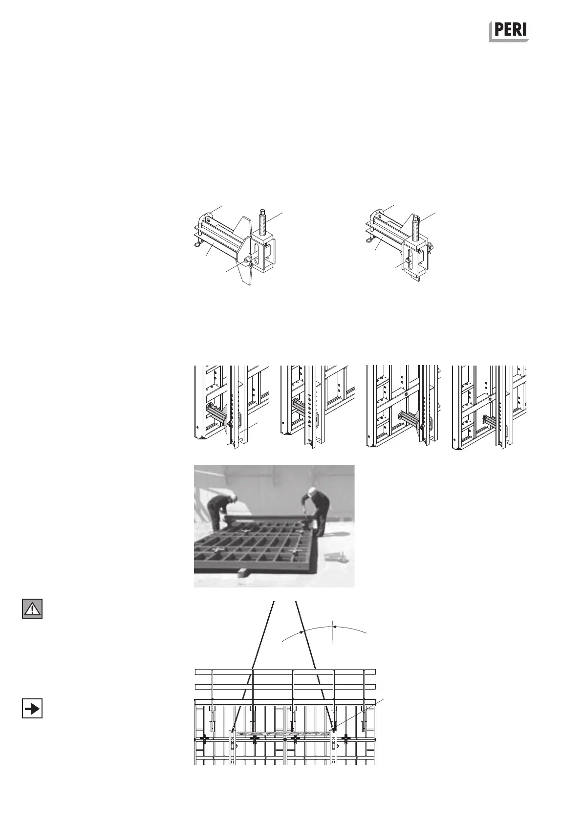
B2 Assembly of formwork elements
TRIO eElement
Mounting of Strongback CB on
TRIOelements
1. Assemble TRIO elements on the
assembly area to form formwork
units.
2. Fix Connector TRIO-CB (4.5) to panel
struts with bail pin Ø 25 (4.7), see
plans for arrangement.
Centre distance = bracket spacing.
By changing the mounting position of
the adjusting spindle (4.8), the Con-
nector TRIO-CB can be used cantile-
vering on the left or right.
(Fig. B2.09 + B2.10)
Connections are possible on horizon-
tal and vertical panel struts through
repositioning of the bail pins.
(Fig. B2.11 - B2.14)
3. Place Strongback CB (4) on the
connectors. Bottom projecting length:
see project drawings or C1.
4. Attach Strongback CB to bottom
connector using bolts and cotter pins
(4.6).
5. Adjust height on bottom connector
using adjusting spindle (4.8).
6. Adjust height of top connector.
7. Fix Strongback CB at top connector
TRIO-CB.
(Fig. B2.15)
In order to prevent the strongbacks
from being pulled out of position at
any time, a piece of timber (4.10) is
clamped between the top ends of
the strongbacks, see also C1 Moving.
(Fig. B2.16)
Alternatively, use Lifting Beam RCS 10 t
(Item no. 112986) for moving.
On horizontal struts
Connector TRIO-CB
left cantilevering right cantilevering
left
cantilevering
right
cantilevering
On vertical struts
left
cantilevering
right
cantilevering
Fig. B2.15
Fig. B2.11 Fig. B2.12 Fig. B2.13 Fig. B2.14
Fig. B2.09
Fig. B2.16
Fig. B2.10