39Instructions for Assembly and Use – Standard Configuration
CB 160 Climbing Formwork
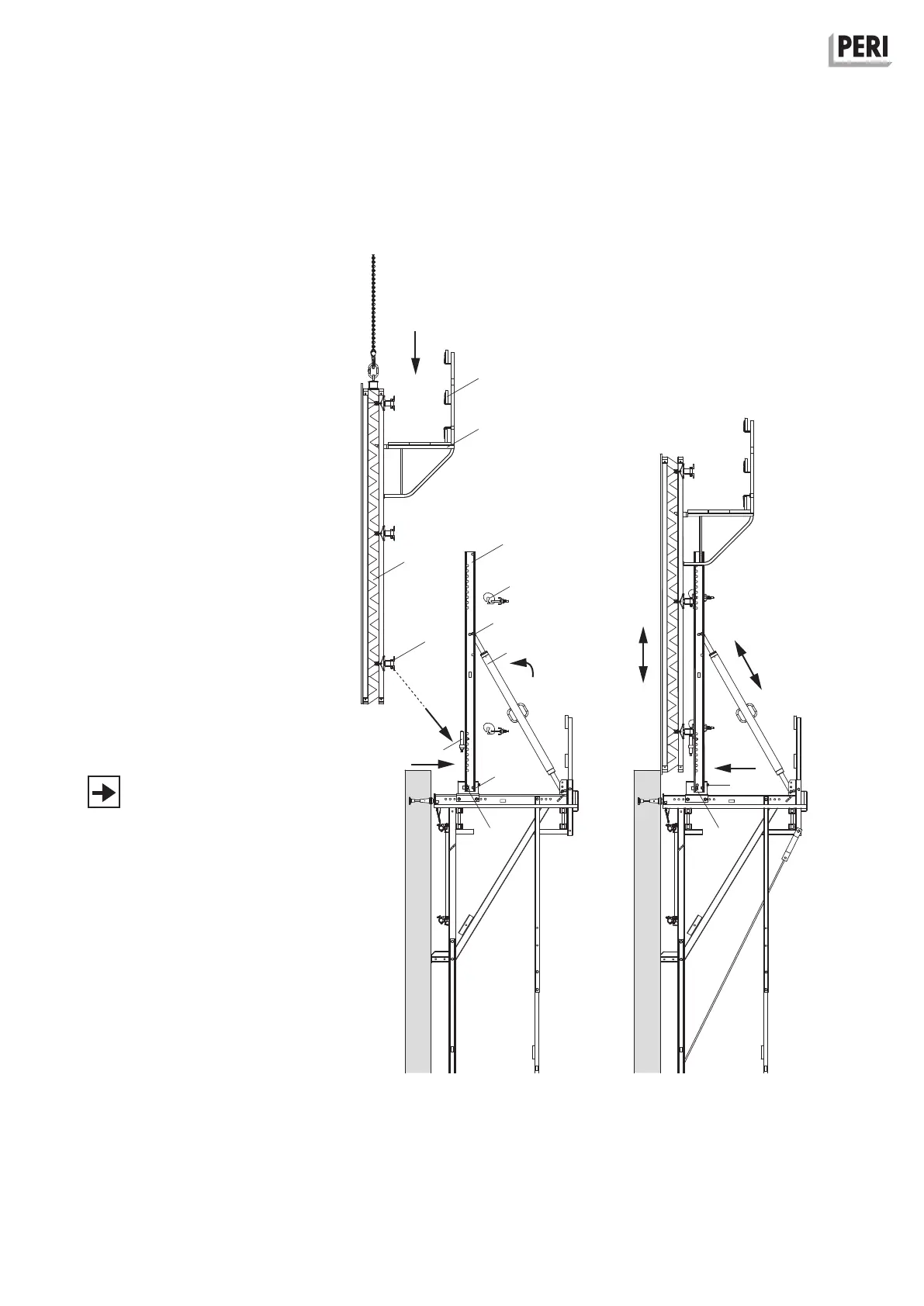
B2 Assembly of formwork elements
VARIO GT 24 element
Moving of VARIO GT 24 elements
Preparation for initial assembly
1. Move back the sliding unit (2.1) in the
adjusting unit, SW 19, see B3.
2. Fix Strongback CB (4) to the adjusting
unit by means of bolts Ø 25 x 180 and
cotter pins (4.6).
3. Attach Adjustable Brace (3.1) to
strongback using bolts Ø 25 x 180 and
cotter pins (3.2) and laterally brace
strongbacks.
Assembly
4. Check that the Height Adjusting Unit
(4.3) is in the correct position and ad-
just if necessary.
5. Lower formwork (10) with the bottom
waler (10.4) onto the height adjusting
unit. Lifting gear remains tensioned.
6. Fix strongback connector (4.4) to the
walers. (Fig. B2.07)
Detach lifting gear.
7. Move sliding block (2.1) in the adjust-
ing unit to the wall, SW 19.
8. Align formwork, see B3.
(Fig. B2.08)
Attention must be paid to ensure that
the strongback does not collide with
the Scaffold Bracket GB 80 (10.2) or
decking (10.3). If necessary, remove
scaffold bracket and decking.
Fig. B2.07 Fig. B2.08
10.2
10.3
10.4
10
4
4.3
3.1
3.2
2.1
4.4
2.14.6
SW 19
SW 19