44 Instructions for Assembly and Use – Standard Configuration
CB 160 Climbing Formwork
B3 Formwork Utilisation
Utilisation of
adjusting unit CB 160
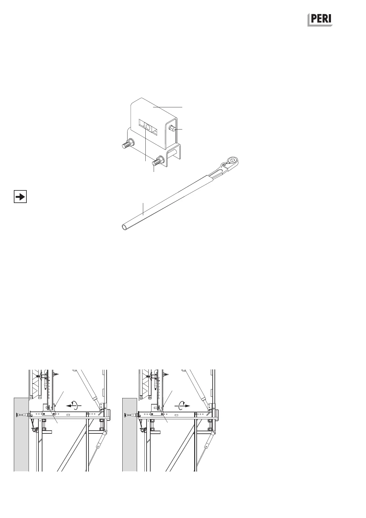
Adjusting Unit
Adjusting Unit CB 160 (2)
Sliding block with hole Ø 26 (2.1)
Adjusting bolt SW 19 (2.2)
Hex. bolt ISO 4014 (2.3)
M20 x 150-8.8 and nut
ISO 7042 (2x)
Ratchet Lever SW 19 (2.5)
(Fig. B3.01)
After using the adjusting unit, the
inclination of the formwork must be
checked and adjusted.
Fig. B3.02
Moving the formwork away from
thewall
Turn the adjusting bolt SW 19 (2.2) in a
clockwise direction. The sliding block
(2.1) then moves away from the wall.
(Fig. B3.03)
Moving the formwork to the wall
Turn the adjusting bolt SW 19 (2.2) in an
anti-clockwise direction. The sliding block
(2.1) then moves to the wall.
(Fig. B3.02)
Adjusting range: max. 7 cm
Fig. B3.03
Fig. B3.01
2
2.2
2.2
SW 19
SW 19
2.1
2.3
2.5
2.1
2.2
10
2.1