8 Instructions for Assembly and Use – Standard Configuration
CB 160 Climbing Formwork
A1 Assembly of the CB 160 platforms
Required resources
Equipment and tools
Hammer, wire pins, plumb line,
4 screw clamps with 300 mm clamping
length, circular saw, electric drill, HSS
drill Ø 6 mm, Ø 8 mm,
min. L = 180 mm.
072180 Ratchet Wrench 1/2”
102784 Socket SW 24 - 1/2”
Wrench SW 24
029620 Socket SW 19 - 1/2”
Wrench SW 19.
072170 Socket SW 13 - 1/2”
072150 Electric Power Wrench
(recommended)
072080 Electric Screw Driver
072090 Bit Holder
072120 Magnetic Holder
072140 Bit Points TX 30
031480 Socket Wrench SW 36
027212 Allen Kew SW 14
031080 Drill Bit Ø 25 mm
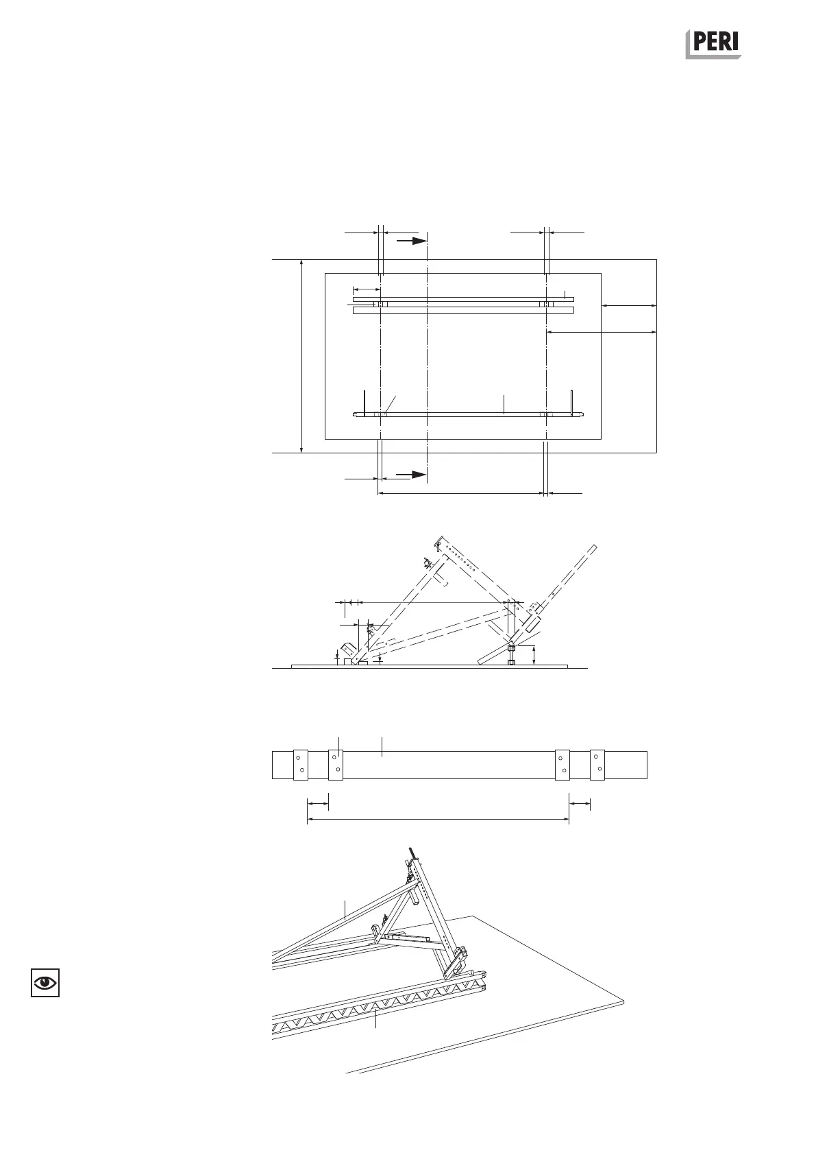
Flat assembly surface
Width: approx. 3.50 m
Length: maximum platform width + 2.0 m
Attach stop bars and support.
(Fig. A1.01)
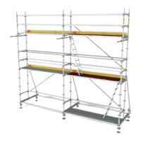
Aids
– Locating block (0.1)
12 plywood blocks 21 x 80 x 80 mm
– Support h = approx. 24 cm,
e.g. GT 24 (0.2)
L = max. bracket spacing + 1.0 m
– Stop bars
1 plank 40 x 120 mm (0.3)
1 plank 80 x 80 mm
L = max. bracket spacing + 1.0 m
– Gauge for bracket spacing C
1 plank 40 x 120 mm (0.4)
L = bracket spacing + max. 1.0 m
plywood blocks (0.1) ( Fig. A1.02)
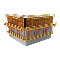
– Diagonal bracing for securing bracket
1 plank 40 x 120 mm, L = 2.0 m (0.5)
(Fig. A1.03)
Are the stop bars and support
mounted in parallel?
0.5
0.2
0.2
24
8
4
12
95
80
1.905 m
8
82 mm 82 mm
1.0 m
2.0 m
3.5 m
62 mm
62 mmC
0.1
0.2
0.1
0.3
Fig. A1.03
Fig. A1.01
approx. 0.50 m
2 stop bars
Support
Centre line of
bracket
Centre line of
bracket
0.1
82 82
C
0.4
Fig. A1.02
Fig. A1.01a
Section A-A
A
A