32
6.4
Z
z
Z
z
Instructions for Assembly and Use – Standard Configuration
CB 160 Climbing Formwork
B1 Work on the construction site
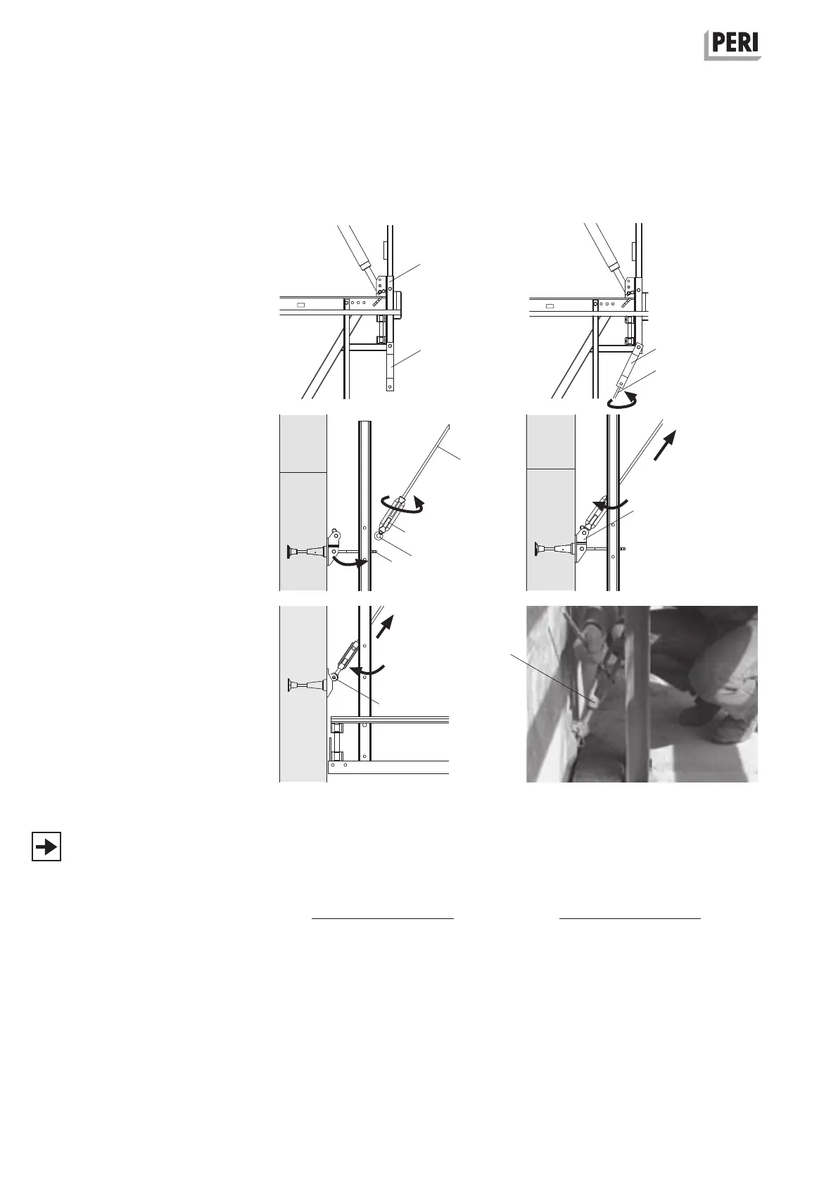
Assembly of wind bracing
With Tie Rod DW 15
Permissible tension anchor force
Z
Z
= 41 kN.
1. Fix Tension Anchor Connector CB (7.3)
with designated Bolt M16 x 100, SW
24, to vertical tube of the bracket
(1.2). (Fig. B1.34a)
2. Screw in the DW 15 Tie Rod (7.4) into
the nut of the Tension Anchor Connector
(6.2). (Fig. B1.34b)
3. Loosen scaffold mounting ring and
Bolt M24 x 120 on the previous con-
creting segment with Socket Wrench
SW 36 and remove. (Fig. B1.31)
4. Fix Bracing Shoe Wall CB M24 (6.1)
to the cone using Bolt M24 x 70
(5.14) SW 36, after the bolts have
been removed from the tension plate
(6.2). Re-insert tension plate through
the platform post and re-bolt in the
bracing shoe.
(Fig. B1.32)
5. Turn Turnbuckle CB Ø 25-M20L/DW
15 (7.6) on the tie rod (7.4) (Fig. B1.34c).
Roughly adjust length by turning the
tie rod. Fine adjustment by turning
the turnbuckle.
6. Insert eyelet bolt Ø 25-M20L (7.5) into
the bracing shoe (6.1) and secure
with designated bolts and cotter pins.
(Fig. B1.34d)
7. Turn turnbuckle, e.g. with shortened
tie rod, thus tensioning the wind
bracing. (Fig. B1.34f)
If lateral stabilisation of the finishing
platform is not required, then the Wall
Tension Anchor (6.4) can also be used.
Loosen turnbuckle, turn on tie rod and
insert into the tension anchor connector.
(Fig. B1.34e)
Fig. B1.34a
Fig. B1.34b
Fig. B1.34c Fig. B1.34d
Fig. B1.34f
L =
√
(H - 22.5)
2
+ 232.6
2
– 51 L =
√
(H - 16.4)
2
+ 233.6
2
– 51
Formula for calculating the length of
the DW 15 Tie Rod.
With Bracing Shoe Wall CB M24
With Wall Tension Anchor
H =
L =
Concreting height in cm = vertical spacing of the climbing anchor
Tie rod length in cm
1.2
7. 3
7. 3
7. 4
7. 6
6.2
7. 5
6.6
6.1
7. 4
Fig. B1.34e