29
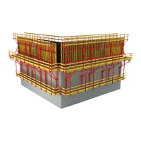
CB 240 Climbing Formwork
Instructions for Assembly and Use – Standard Configuration
B1 Work on the Construction Site
5.10
3 cm
4 cm
5
5.10
5.9
5.13
3 cm
4 cm
5.4
Anchoring
Assembly of the Leading Anchor
With Advancing Bolt M24, e.g. for
VARIO GT 24 Girder Wall Formwork.
Initial Use
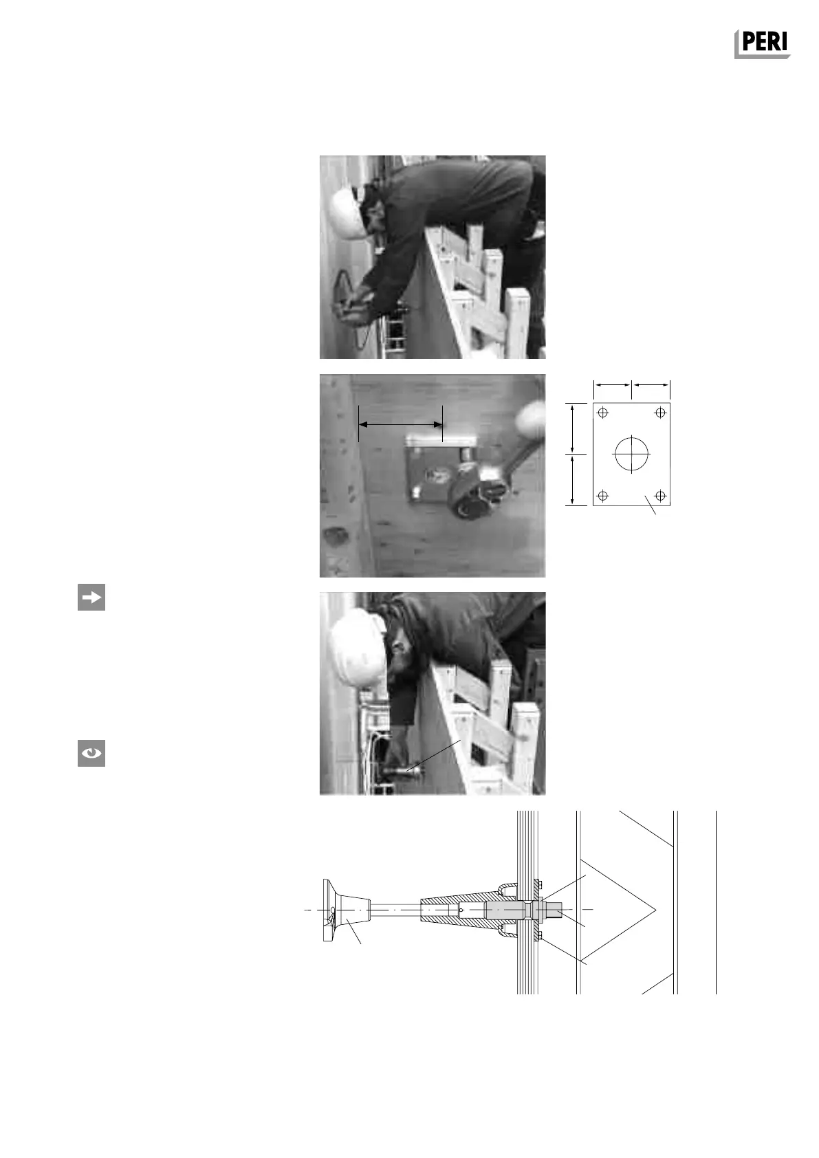
1. Check the required space for the An-
chor Positioning Plate M24 (5.10). A
lateral clearance of 3 cm or 4 cm is
required. (Fig. B1.10)
2. Determine the set position and drill
Ø25 mm hole from the front of the
formwork. (Fig. B1.09)
3. Mount Anchor Positioning Plate M24
(5.10) to the rear side of plywood.
Wood screws 6 x 20 DIN 571,
SW 10 (4x) (5.13). (Fig. B1.10)
Standard Use
1. Insert the Advancing Bolt M24 (5.9)
from the rear side of the plywood
through the drilled hole.
2. From the front side of the plywood, ti-
ghtly screw on the Leading Anchor (5).
(Fig. B1.11 + B1.12)
– If there is a formwork girder positi-
oned at the rear of the anchoring,
“Assembly with Anchor Positioning
Stud M24” can be applied.
– For safety reasons, firmly connect the
Threaded Anchor Plate (5.4) to the
reinforcement.
Check Assembly
– height,
– anchor spacings,
– anchoring depth h,
– alignment according to specifications.
Checking the Leading Anchor and rein-
forcement measures can be done at the
same time.
Fig. B1.09
Fig. B1.10
Fig. B1.11
Fig. B1.12
min. 3 cm
AuV CB 240 EX.indb 29 29.06.16 09:44
 Loading...