Home
Phoenix Contact
Controller
AXC F 3152
Phoenix Contact AXC F 3152 User Manual
5
of 1
of 1 rating
113 pages
Give review
Manual
Specs
To Next Page
To Next Page
To Previous Page
To Previous Page
Loading...
AXC
F
X152
84 / 112
PHOENIX CONTACT
107708_en_08
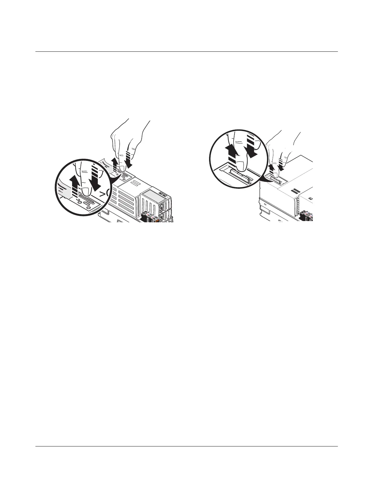
10.4
Removing the SD card
•
Lightly push the SD card fa
r enough into the SD card holder until th
e snap-in mecha-
nism releases the SD card and partially ejec
ts the SD card from the SD card holder.
•
Remove the SD card.
Figure
10-4
Removing the SD card
AXC
F
1152 and AXC
F
2152
AXC
F
3152
R
S
D
-C
A
R
D
X4
X2
X1
>Click<
>Click<
83
85
Table of Contents
Table of Contents
3
Default Chapter
2
Axc F 2152
2
Table of Contents
3
1 For Your Safety
7
Identification of Warning Notes
7
Qualification of Users
7
Field of Application of the Product
8
Intended Use
8
Product Changes
8
Safety Notes
8
Security in the Network
9
UL Warning Notes
10
Notes on Using the AXC F 2152 Controller in Potentially Explosive Areas
10
Temperature Derating of the AXC F 2152 Depending on the Alti
11
2 Transport, Storage, and Unpacking
12
Transport
12
Storage
12
Unpacking
12
3 Description of the Controllers
14
General Description of the Controllers
14
Components of the Controller
14
Axioline F Extension Module
15
Licensing Information Regarding Open-Source Software
17
Requesting the Source Code
17
Directory Structure of the File System
17
Using SFTP to Access the File System
18
Administrator Password on the Controller
18
Firewall
19
Possible Fields of Application of the Controller
19
Example: Axioline F Station with AXC F 2152 Controller
19
The Controller as a Distributed Controller of an Axioline F Station
19
Example: AXC F 3152 Controller as Profinetcontroller
20
The Controller as a PROFINET Controller in a PROFINET Network
20
Example: AXC F 3152 Controller as PROFINET Device
21
The Controller as a PROFINET Device in a PROFINET Network
21
Components of the Controller
22
Connection and Operating Elements
22
Connection and Operating Elements of the AXC F 1152 and
22
Connection and Operating Elements of the AXC F 3152 Control
23
AXC F 1152 and AXC F 2152 Controller Printing
24
AXC F 3152 Controller Printing
24
Printing
24
Diagnostic and Status Indicators
26
Mode Selector Switch (AXC F 3152)
30
Mode Selector Switch on the AXC F 3152 Controller
30
Reset Button
31
Sequence When Resetting to Default Setting Type 1, and LED Indicators
32
Sequence When Resetting to Default Setting Type 2, and LED Indicators
32
Parameterization Memory
33
SD Card (Optional)
33
Internal Basic Circuit Diagram
36
Internal Basic Circuit Diagram for AXC F 1152 and AXC F 2152
36
Internal Basic Circuit Diagram AXC F 3152
37
Communication Paths
38
Ethernet
39
Supply Connector
39
Terminal Point Assignment of the Supply Connector
39
Terminal Points for the Supply Voltage
39
Bus Base Module
40
Structure of the AXC BS L 2 Bus Base Module
40
Structure of the AXL BS BK Bus Base Module
40
Structure of the AXC BS L 30 Bus Base Module
41
4 Mounting Hardware
42
Safety Notes
42
Basic Information
43
Example: AXC F 2152 in Horizontal (A) and Vertical (B) Installa
44
Structure of an Axioline F Station
45
Example: Structure of an Axioline F Station with the
45
Example: Axioline F Station with AXC F 3152 and Left-Aligned
46
Structure of a Plcnext Inline Station
47
Example: Structure of a Plcnext Inline Station with the
47
Mounting the Controller
48
Mounting the Bus Base Modules
48
Snapping the Controller into Place
48
Inserting the SD Card
49
Removing the Upper Marking Field of the AXC F 1152 and
49
Mounting a Left-Alignable Axioline F Extension Module
50
Mounting the AXC F IL ADAPT Inline Adapter Terminal
50
5 Connecting and Wiring Hardware
51
Supply Voltage
51
Overload Range with Fall-Back Characteristic Curve
51
Overload Range Without Fall-Back Characteristic Curve
51
Sizing of the Power Supply
51
Connecting the Power Supply
52
Connecting the Supply Connector
53
Connecting Ethernet
54
6 Startup
55
Installing Plcnext Engineer
55
User Interface
56
Plcnext Engineer User Interface
56
Creating a New Project
57
Configuring the IP Settings
58
Setting the IP Address Range
58
Start Page, "Empty AXC F 2152 V.00 / 2020.0.0 Project" Proj
58
Setting the IP Address
60
Connecting to the Controller
61
Successful Assignment of the Configured Controller to an on
62
7 Transferring Variable Values to PROFICLOUD
64
8 System Variables and Status Information
65
General Information
65
Data Structures
65
Example of AXC F 2152: Init Value Configuration for the RTC System Variable Organized as a Data Structure
66
System Time
67
Power Supplies
67
TCP_SOCKET, UDP_SOCKET, and TLS_SOCKET Function Blocks
67
Power Supply System Variables
67
RTC System Variable (RTC_TYPE Data Structure) and the System Variables It Contains
67
System Variables for the TCP_SOCKET, UDP_SOCKET, and
67
Device Status
68
DEVICE_STATE System Variable
68
Partition
69
USER_PARTITION System Variable
69
Task Handling
70
ESM_DATA System Variable (ESM_DAT Data Structure) and the System Variables It Contains
70
Client Connections to a Plcnext Engineer HMI Web Server
72
HMI_STATUS System Variable
72
HMI_STATUS System Variable (HMI_STATUS_TYPE Data Struc- Ture) and the System Variables It Contains
72
HMI_CONTROL System Variable
73
Axioline F: Diagnostic Status Register
74
System Variables of the Diagnostic Status Register
74
Axioline F: Diagnostic Parameter Register
75
System Variables of the Diagnostic Parameter Register
75
PROFINET System Variables
76
PROFINET System Variables (PROFINET Controller Functionality)
76
INTERBUS: Master Diagnostic Status Register
78
Ler
78
PROFINET System Variables (PROFINET Device Functionality)
78
System Variables of the Master Diagnostic Status Register
78
INTERBUS: Master Diagnostic Parameter Register
79
Error Code in the Master Diagnostic Parameter Register
79
Error Location in the Master Diagnostic Parameter Register
79
Example for Error Code 0A050
79
System Variables of the Master Diagnostic Parameter Register
80
9 Web-Based Management (WBM)
81
10 Removing Hardware
82
Safety Notes
82
Removing Cables
83
Removing the Connector
83
Removing the SD Card
84
Removing the Controller
85
Removing a Left-Alignable Axioline F Extension Module
85
Removing the AXC F IL ADAPT Inline Adapter Terminal
85
11 Device Replacement, Device Defects, and Repairs
86
Device Replacement
86
Device Defects and Repair
87
12 Maintenance, Decommissioning, and Disposal
88
Maintenance
88
Decommissioning and Disposal
88
13 Troubleshooting and Frequently Asked Questions (Faqs)
89
14 Ordering Data and Technical Data
91
Ordering Data
91
Overview of Documentation
92
Technical Data of the AXC F 1152 and AXC F 2152
93
AXC F 3152 Technical Data
98
A Appendix
102
A 1 Updating the Firmware Via the Shell
102
A 2 Shell Commands for Controlling the Firmware
102
A 3 Replacing the HTTPS Certificate
102
A 4 Use of the AXC F 2152 Controller under Extreme Ambient Conditions
103
B Appendix For Document Lists
104
List of Figures
104
B 2 List of Tables
107
Index
108
Other manuals for Phoenix Contact AXC F 3152
User Manual
106 pages
5
Based on 1 rating
Ask a question
Give review
Questions and Answers:
Need help?
Do you have a question about the Phoenix Contact AXC F 3152 and is the answer not in the manual?
Ask a question
Phoenix Contact AXC F 3152 Specifications
General
Brand
Phoenix Contact
Model
AXC F 3152
Category
Controller
Language
English
Related product manuals
Phoenix Contact AXC F 1152
113 pages
PLCnext AXC F 2152
9 pages
Phoenix Contact ILC 191 ME/AN
168 pages
Phoenix Contact IBS ABB DSC-T
118 pages
Phoenix Contact ILC 150 ETH
78 pages
Phoenix Contact ILC 2050 BI
76 pages
Phoenix Contact ILC 330 Series
96 pages
ELR W3 500AC I Series
56 pages
EV Charge Control Basic
70 pages
ELR H5-IES-SC-24DC/500AC-2
56 pages
ELR H5-IES-SC-24DC/500AC-9
56 pages
ELR H5-IES-SC-24DC/500AC-0,6
56 pages