Connecting and wiring hardware
107708_en_08 PHOENIX CONTACT 53 / 112
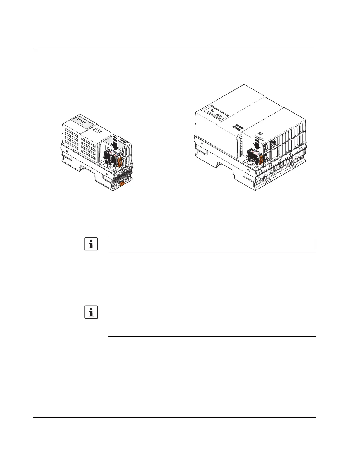
Connecting the supply
connector
• Place the supply connector vertically into its position and press down firmly. Make sure
that the locking latch snaps into place.
Figure 5-5 Connecting the supply connector
Supply the controller via external 24 V DC sources. The permissible voltage range is
19.2 V DC to 30 V DC (ripple included).
1. Connect the power supplies to the supply connector as shown in Figure 5-3 and in
Figure 5-4. Note the information in Section 3.16.
2. Switch on the power supplies.
The controller is now fully initialized.
If the LEDs do not light up or start flashing, there is a serious fault in the controller. In this
case, please contact Phoenix Contact.
AXC F 1152 and AXC F 2152 AXC F 3152
Only use power supplies that are suitable for operation with capacitive loads (increased
inrush current) (see Section 5.1.1).
Please note the following when using left-alignable Axioline F extension modules:
The supply voltage of the controller and the left-alignable Axioline F extension modules
must be fed in via a shared power supply unit.
• Connect the supply voltage as described in the module-specific data sheet.
 Loading...


