Removing hardware
107708_en_08 PHOENIX CONTACT 85 / 112
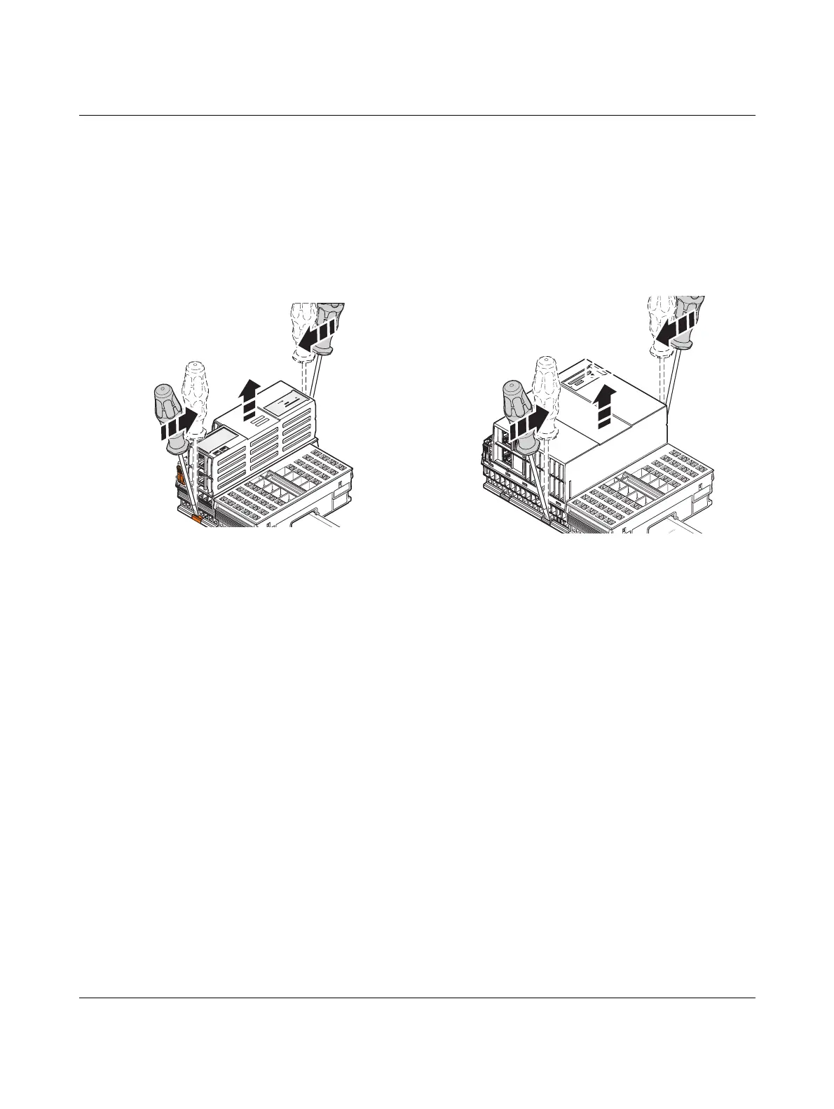
10.5 Removing the controller
• Insert a suitable tool (e.g., bladed screwdriver) into the upper and lower snap-in mech-
anisms (base latches) of the controller one after the other and release the controller (A
in Figure 10-5).
The base latches are locked in place in the open position.
• Remove the controller keeping it perpendicular to the DIN rail (B in Figure 10-5).
Figure 10-5 Removing the controller
10.6 Removing a left-alignable Axioline F extension
module
• Remove the left-alignable Axioline F extension module as described in the module-
specific packing slip.
10.7 Removing the AXC F IL ADAPT Inline adapter ter-
minal
• Remove the Inline adapter terminal as described in the module-specific packing slip.
AXC F 1152 and AXC F 2152 AXC F 3152
 Loading...


