Mounting hardware
107708_en_08 PHOENIX CONTACT 45 / 112
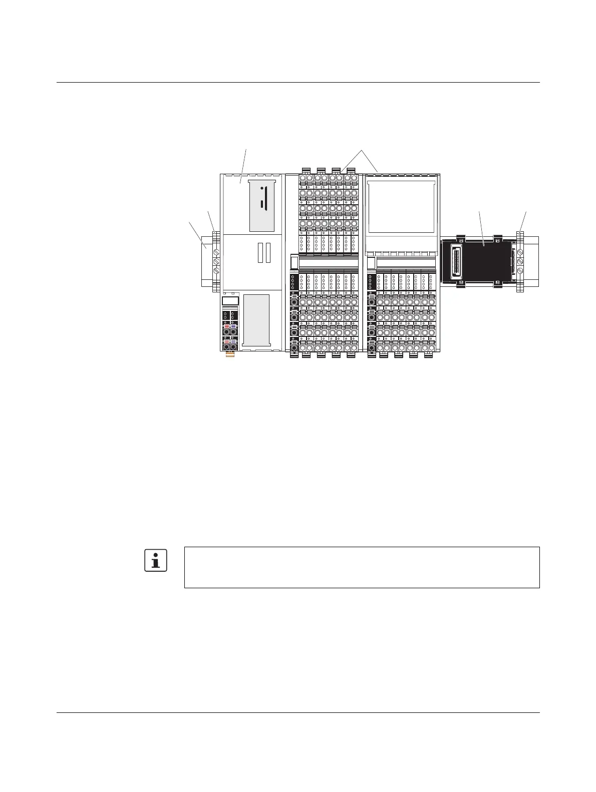
4.3 Structure of an Axioline F station
Figure 4-3 shows an example structure of an Axioline F station with the AXC F 2152:
Figure 4-3 Example: Structure of an Axioline F station with the AXC F 2152
Key:
1 DIN rail
2 End bracket (e.g., CLIPFIX 35-5; Order No. 3022276)
3 Controller
4 I/O modules (Axioline F devices) corresponding to the application
5 Bus base module
An Axioline F station is set up by mounting the individual components side by side. No tools
are required. Mounting the components side by side automatically creates potential and bus
signal connections between the individual components of the Axioline F station.
Left-alignment of
Axioline F extension
modules
– You can connect one Axioline F extension module to the left of the AXC F 2152 using
the AXC BS L 2 bus base module.
– You can connect one AXC F XT IB Axioline F extension module to the left of the
AXC F 3152 using the supplied AXC BS L 30 bus base module. Connection of the left-
alignable AXC F XT ETH 1TX Ethernet interface is not supported yet.
– Axioline F extension modules cannot be aligned to the left of the AXC F 1152.
Please note:
The AXC BS L 2 bus base module is not supplied with the AXC F 2152. For the bus base
module ordering data, please refer to Section “Ordering data” on page 91.
 Loading...


