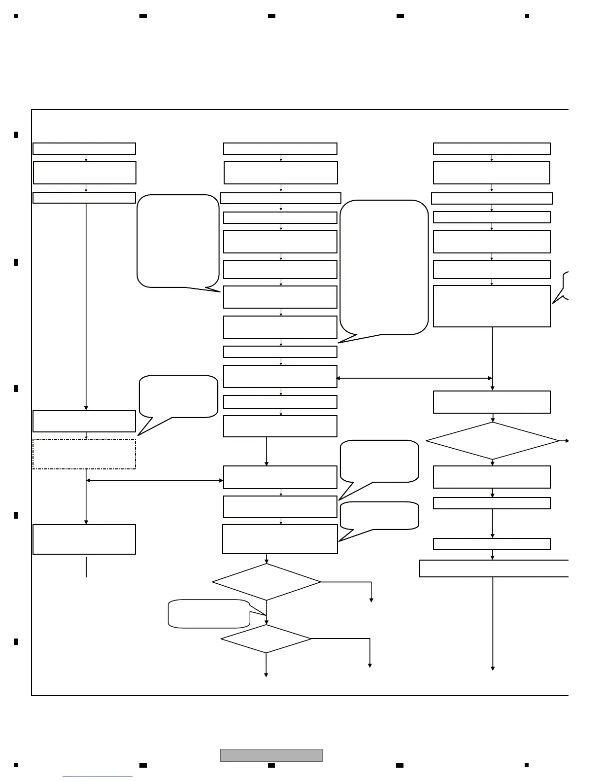
5. DIAGNOSIS
[1] Operation sequence after power-on of the MEP-7000 (Normal Style)
ATAPI Drive Drive Unit
Power-on
Power-on
Canceling reset of SODC
(IC106/906) at Pin 45
Canceling reset of the SOUTH
CPU (IC202) at Pin 13
Initial setting
Initialization of the SDRAM
Program transfer from the
flash memory to SDRAM
Canceling reset of the
AUDIO DSP
Program transfer to the
AUDIO DSP (IC501)
Program transfer to the
FPGA (IC301)
Canceling reset of the FPGA
Starting communication
with the control unit
Canceling reset of DAC
Initializing the Loading
mechanism
Canceling reset of the
ATAPI system
Once a disc is inserted,
the process for
loading and startup starts.
Starting communication
with the ATAPI system
Checking the
peripheral devices
Once a disc is inserted,
the process for
loading and startup starts.
Process with the keys held
pressed for several seconds
during power-on
Data reading, etc.
Process for CD playback
S
Process for DVD playback
Afterwards, processes for key-status
input and display data output follow.
The “PIONEER” and “PRO DJ” indications
Judging of DVD/CD
A disc can be loaded
before starting
communication
with the MAIN Assy.
If a disc is loaded,
the process for
playback starts.
Data and clock signals
are output from Pins
55 and 53 of the
SOUTH CPU (IC202),
respectively.
After transfer to
the FPGA
is completed, FDONE
(Pin 37) becomes high.
For details on the
downloading sequence,
see “[3] Downloading
Sequence.”
Items with NG
check results can be
confirmed in
Service mode.
Data and clock signals
are output from Pins
55 and 53 of the CPU
(IC202),respectively.
For details on the
downloading
sequence,see
“[3] Downloading
Sequence.”
Check if the unit
is in Service mode.
Is the Drive Unit
in Service mode?
Ye s
DVD
CD
No
Control Unit
(Normal Style)
Power-on
Canceling reset of the NORTH
CPU (IC601) at Pin 13
Initial setting for the NORTH CPU
Initialization of the SDRAM
Program transfer from the
flash memory to SDRAM
Canceling reset of the
video encoder
Process of reading data
with the keys held pressed
for several seconds
during power-on
The “PIONEER” and “PRO DJ”
indications appear on the LCD.
The LOOP IN and LOOP OUT
LEDs light.
The OEL displays “EJECT.”
The OEL displays “noDISC.”
Ye s
No
Is the Control Unit
in Service mode?
Service mode indication
Initial setting for the SOUTH CPU
 Loading...