It must be clarified whether the
problem is caused by the disc or
player. Check if the recording
surface of the disc is stained.
If the disc is apparently dirty, replace the CD
with one in good condition.
-
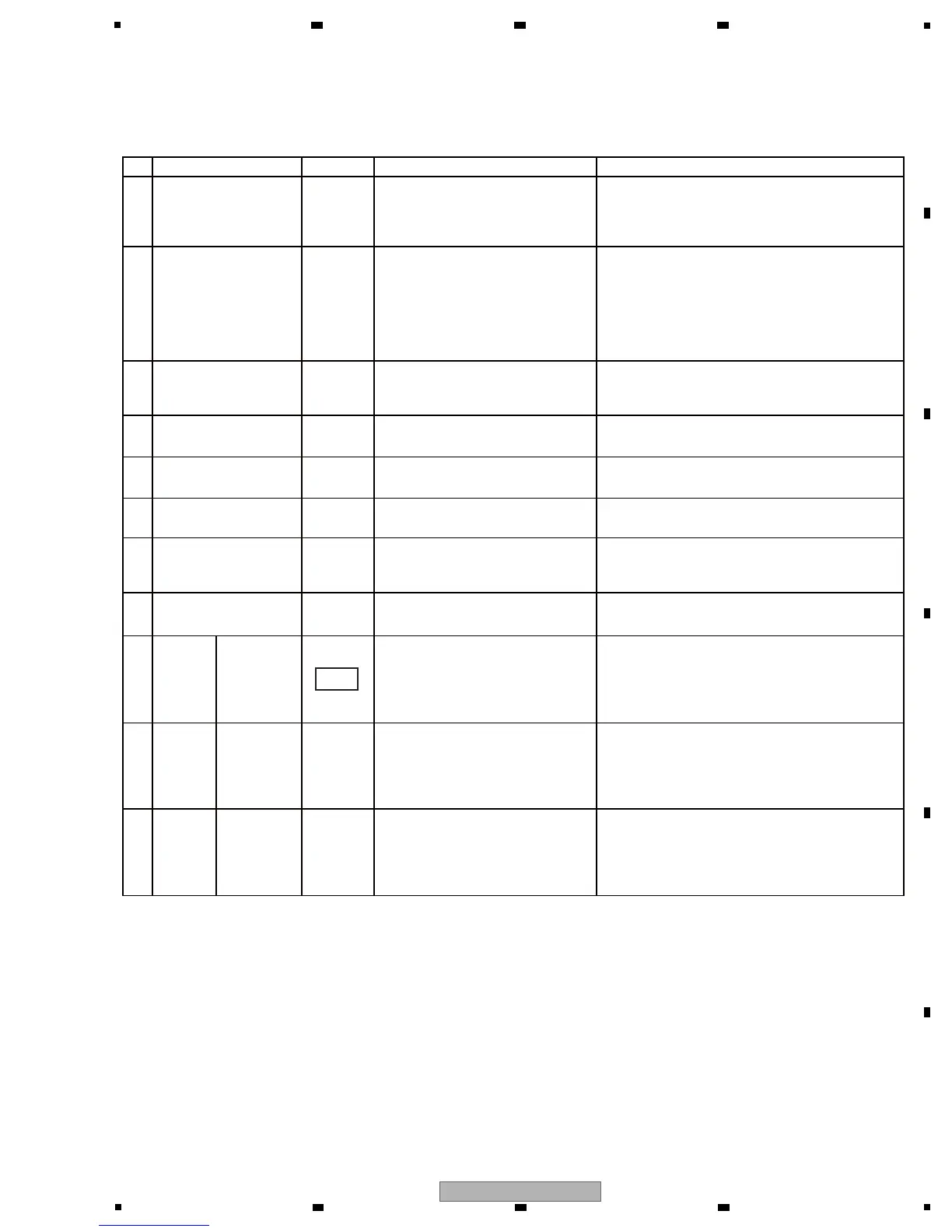
No. Waveform Items for check Causes and measuresPoints to be checked
[7-1] The error rate is judged as NG in Player Operation mode
1 DISC
Using the disc with which the
error rate was judged as NG,
measure the error rate, using
addresses in different area. If the
error rate can be measured with
those addresses, that CD is
defective.
If the error rate can be measured with the
addresses in different areas, the CD is
defective; replace it with one in good condition.
If the error rate cannot be measured in any
area of the disc, go to [3].
-2 DISC
Check if shavings or dirt are
attached to the lens on the
Pickup Assy.
Clean the lens.
-3
TRAVERSE
MECHANISM
Check that the Traverse mecha-
nism is securely attached.
If it is not, reattach it securely.
-4
TRAVERSE
MECHANISM
Check that the Loading Mecha-
nism Assy is securely attached.
If it is not, reattach it securely.
-5
TRAVERSE
MECHANISM
Check if any foreign object is on
the spindle table.
Remove the foreign object, if any.
-6
TRAVERSE
MECHANISM
For details, see “5.4 DEFECT JUDGMENT OF
THE PICKUP ASSY.”
--8 -
Check if any foreign object is
attached to the magnet block of
the Pickup Assy.
Remove the foreign object, if any.
-
-
7
TRAVERSE
MECHANISM
Check if the quality of the RF,
ARF, and NARF waveforms are
similar.
with the
DVD/CD
drives
removed
If they are not, check the mounting status of
IC102.If it is properly mounted, the port
connector may be defective; replace it.
9
SRV1/2
ASSY
Check that the RW/XR (Pin 18 of
CN100/900) signal becomes H
when a disc is played back.
with the
bottom
plate of the
unit
removed.
If the signal remains L, check the mounting
status of IC106. If it is properly mounted, the
port connector may be defective; replace it.
10
SRV1/2
ASSY
-
Check the ripple of the input
voltage of V+8D and V+5SD
power.
with the
DVD/CD
drives
removed
If the capacity of the switching power unit is
insufficient, replace it.
11
SRV1/2
ASSY
47,48
[7] SERVICE MODE
Refer to the descriptions of “6. SERVICE MODE.”
 Loading...