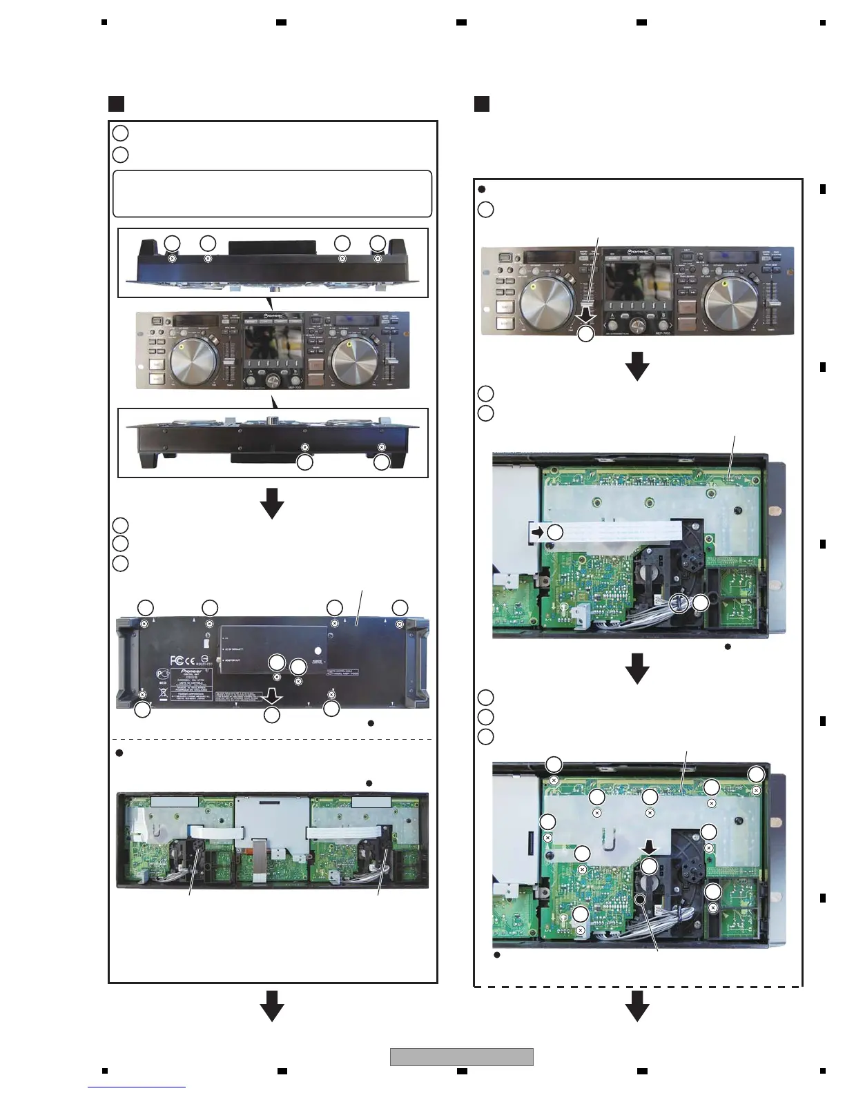
7.2 CONTROL UNIT
Rear view
Rear view
Rear view
Rear view
DISP Assy
DISP Assy
∗ (Jog dial fixed screw ×3)
1
2
3
4
5
1
4
4
3333
5
5
5
55
5
5
5
4
4
4
4
2 2
1 1 1
5
6
2
3
1
1
2
3
5
4
6
DISP Assy
CONTROLLER A CONTROLLER B
Rear panel
Slide knob
Adjust plate Adjust plate
Remove the four screws.
Remove the four screws.
Remove the rear panel.
Remove the slide knob.
Disconnect the flexible cable.
Release the jumper wire.
Remove the eight screws.
Remove the two screws.
Remove the DISP Assy.
Position of the Adjust plate
About details of Adjustment etc., refer to the
“8.1 Mode for checking load on the JOG dial and
Adjustment” in “8. EACH SETTING AND
ADJUSTMENT”.
Rear Panel
1
Remove the four screws.
Remove the two screws, and remove upper bracket.
JOG Section
2
Note:
The procedure to show below is only CONTROLLER A
side.
As for CONTROLLER B side, the procedure is the same.
Note:
When reassembling the upper bracket,
tighten the screws in the order of A, B, C, then D.
AB C D
 Loading...