8 V
DRIVE UNIT
Has the updating of the firmware
for the control unit failed?
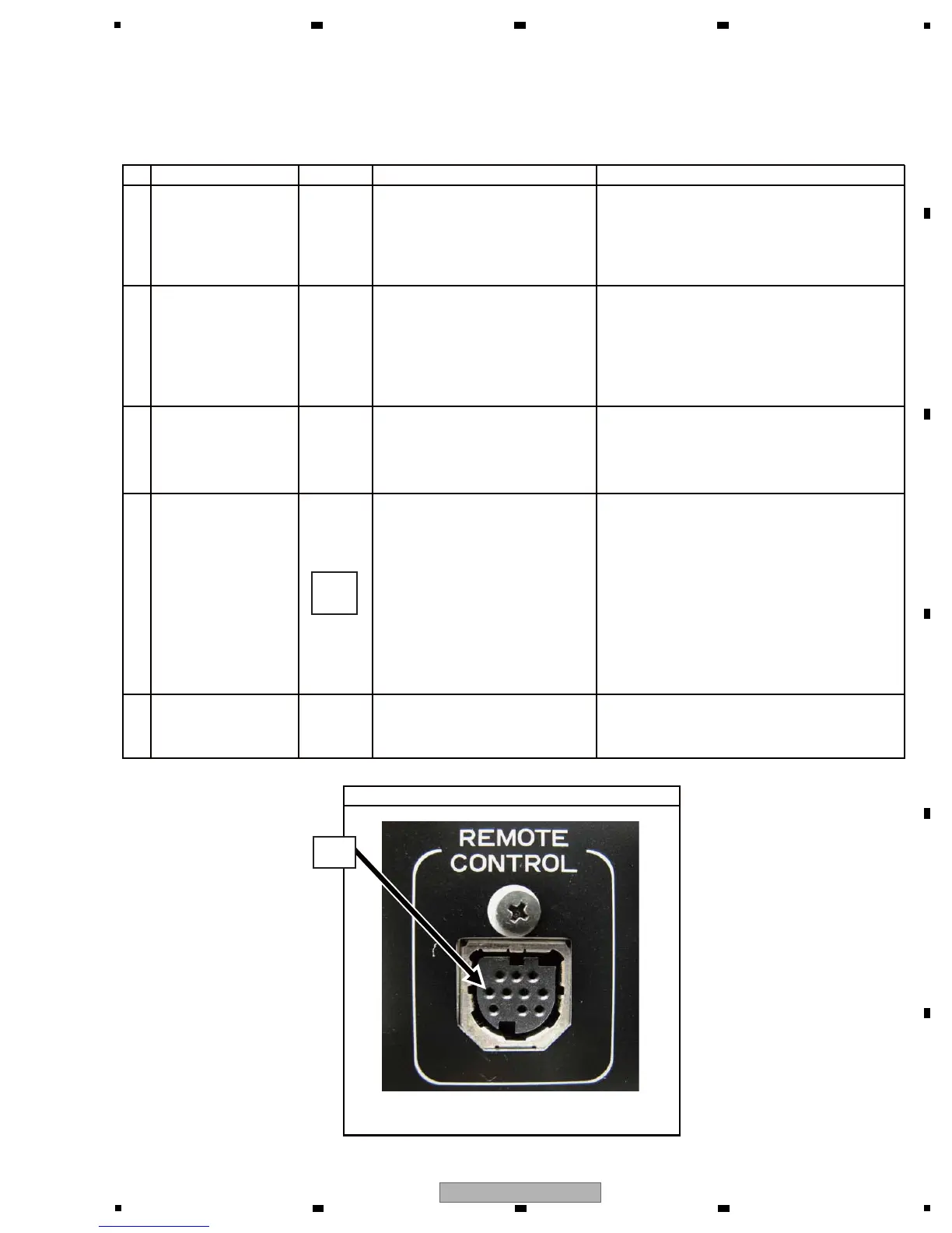
Check that an 8 V voltage is
output from Pin 7 or 10 of the
JA13 jack on the remote control
connector of the drive unit.*2
Check if the cables that connect
the DJACK and NJACK Assys
and NMAIN and NJACK Assys
are securely connected and if
there is breakage in the cables.
If the LED (D601) on the NMAIN
Assy is lit, the power delivery
circuit from 8 V to 3.3 V has risen.
Check the voltages at later
stages.
Check the voltages (V+8D, V+5D,
V+BF3R3D, V+BF1R2D, etc.) on
the NMAIN Assy, referring to “[3]
POWER DELIVERY” in “4.3
BLOCK DIAGRAM”
If the problem is not resolved, the
NORTH CPU (IC601) may not
have properly started up.
If updating fails, operation stops, none of the
LCD, OEL, nor LEDs light, and the LED for the
USB STOP key flashes repeatedly.
See [4] in “8.3 UPDATING/RECOVERY OF
FIRMWARE.”
If an 8 V voltage is output, the control unit is in
failure. If 8 V voltage is not output, the protector
(P101) on the SMAIN Assy may be damaged.
Check the potential difference between the two
electrodes.
If the protector is defective; replace it.
If the LED (D601) is not lit, the power supply
section from 8 V to 3.3 V is in failure.
Check the mounting status of the regulator IC
and its peripheral parts. If they are properly
mounted, they are defective; replace them.
If a connection is loose, firmly connect the
cables.
If there is breakage, replace the cable.
See “[8] Auto Device Diagnosis/Status LEDs”
in this section.
[3-1] The control unit does not start (no LCD, OEL, LEDs light)
[3] CONTROL UNIT (Normal Style)
The following troubleshooting items are applicable when the control unit is connected with the drive unit.
The items specific to Manipulator Style are described in “[4] CONTROL UNIT (Manipulator Style).”

 Loading...