No. Waveform Items for check Causes and measuresPoints to be checked
1
2-
1-
2
3
4
5
6
7-
8 -
NMAIN ASSY
NMAIN ASSY
NMAIN ASSY
NMAIN ASSY
NMAIN ASSY
NMAIN ASSY
NMAIN ASSY
An image is displayed on the monitor connected via MONITOR OUT but not on the center display.
NMAIN ASSY
NMAIN ASSY
NMAIN ASSY
123
105~
109
105~
109
105~
109
118
118
[3-2] Nothing is displayed on the center display nor/or a monitor connected via MONITOR OUT
*3
0
0.2
0.4
0.6
0.8
1
12345
LCD brightness
Voltage of LCD center
LUMICON [V]
Nothing is displayed on the center display nor a monitor connected via MONITOR OUT.
Identical image data are displayed on the LCD display and the monitor connected via MONITOR OUT.
Check that the H sync and V sync
signals are output from the
NORTH CPU (IC601).
If the sync signals are not output, check the
mountingstatus of the IC. If it is properly
mounted, the port connector may be defec-
tive; replace it.
If the RGB data signals do not fluctuate
between H and L, check the mounting status
of the IC.
If it is properly mounted, replace the NMAIN
Assy.
If it is not, securely connect it.
If it is, go to [5].
If it is not, check [3] and [4] below.
If the DISP ASSY ON signal and LUMICON
signal are OK, the Backlight PWR IC (IC700)
may be improperly mounted or defective.
Replace the NMAIN Assy.
If the DISP ON signal does not become H,
check the mounting status of the CENTER
PANEL microcomputer (IC800).
If it is properly mounted, the port connector
may be defective; replace it.
If the LUMICON signal is not output, check
the mounting status of the CENTER PANEL
microcomputer (IC800).
If it is properly mounted, the port connector
may be defective; replace it.
If power is not supplied, check the mounting
status of the regulator IC that corresponds to
that voltage and its peripheral devices. If they
are properly mounted,they are defective;
replace them.
Check the mounting status of the devices from
the crystal oscillator (X700) to the LCD.
If they are properly mounted, they may be
defective; replace them.
If no signal is output even if there is an input
signal, check the mounting status of the level
shifter (IC702/IC703). If they are properly
mounted, the port connector may be defective;
replace it.
Replace the LCD panel.
Check if the FPC board for the LCD
is securely connected.
Check if the power voltage
(V+LCDVF) for driving the
backlight is supplied.
If the DISP ON signal (H when the
display is ON) is output from the
CENTER PANEL microcomputer
(IC800) and input to the Backlight
PWR IC (IC700) and the LCD.
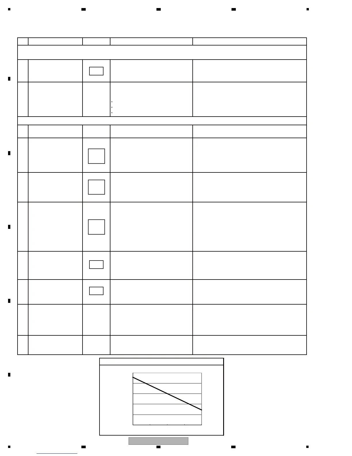
Check the waveform to see if the
LUMICON signal is output from the
CENTER PANEL microcomputer
(IC800) and input to the Backlight
PWR IC (IC700).
The relationship
between the LUMICON signal and
the brightness of the LCD is
indicated in the figure below.*3
Check if the power voltage
(V+5D, V+2R5D) to drive the LCD
is supplied.
Check if the clock signal (9 MHz)
is input to the LCD.
Check the input and output
signals to/from the level shifter
(IC702/IC703).
If the problem is not resolved
even after the above-mentioned
measures are taken.
Check if the following RGB data
signals are output from the NORTH
CPU (IC601):
R3-7 signals
G3-7 signals
B3-7 signals
 Loading...