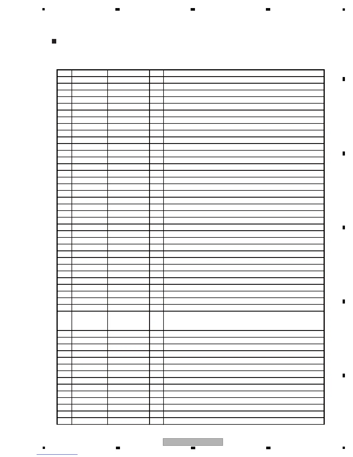
[1] SOUTH CPU(ADSP-BF531SBSTZ400) (SMAIN ASSY : IC202)
ADSP-BF531SBSTZ400, XC3S50-4TQG144C, PDY084A8, PEG481A, PEG480A
List of Items
PIN PORT NAME SIGNAL NAME I/O PIN FUNCTIONS
1GND1
DGND
-GND
2GND2
DGND
-GND
3GND3
DGND
-GND
4 VROUT1 - O Not used (open)
5 VROUT0 - O Not used (open)
6 VDDEXT1 V+3R3D - I/O power supply input (3.3 V)
7GND4
DGND
-GND
8 GND5
DGND
-GND
9GND6
DGND
-GND
10 CLKIN CLKIN I CPU clock input (24.576 MHz)
11 XTAL XTAL O CPU clock output (24.576 MHz)
12 VDDEXT2 V+3R3D - I/O power supply input (3.3 V)
13 /RESET RST# I Reset input
14 NMI - I Not used (connect to GND)
15 GND7
DGND
-GND
16 RTXO - O Not used (open)
17 RTXI - I Not used (connect to GND)
18 VDDRTC - - Not used (connect to 3.3 V)
19 GND8
DGND
-GND
20
VDDEXT3 V+3R3D - I/O power supply input (3.3 V)
21 PPI_CLK - I Not used (connect to GND)
22 PPI0 - O Not used (open)
23 PPI1 - O Not used (open)
24 PPI2 - O Not used (open)
25 VDDINT1 V+1R2BD - CPU core power supply input (1.2 V)
26 PPI3 - O Not used (open)
27 PF15 DSPDREQB# I DSP data request of audio output B
28 PF14 DSPDREQA# I DSP data request of audio output A
29 PF13 USBIRQ# I USBIC interrupt request
30 GND9
DGND
-GND
31 VDDEXT4 V+3R3D - I/O power supply input (3.3 V)
32 PF12 ATA2_IRQ I FPGA-ATAPI data read request of drive 2
33 PF11 ATA1_IRQ I FPGA-ATAPI data read request of drive 1
34 PF10 BRDG_CS# I Control input of control unit communication
35 PF9 - O Not used
36 PF8 FINIT#/SD2_OUT I
FPGA configuration initialization
(top and bottom communication data are input after the initialization is
completed, but do not monitor it.)
37 PF7 FDONE I FPGA initialization is completed
38 PF6 FPRGM O FPGA configuration program
39 GND10
DGND
-GND
40 GND11
DGND
-GND
41 GND12
DGND
-GND
42 GND13
DGND
-GND
43 GND14
DGND
-GND
44
GND15
DGND
-GND
45 VDDEXT5 V+3R3D - I/O power supply input (3.3 V)
46 PF5 FPGARST# O FPGA reset
47 PF4 DSPRST# O DSP reset
48 PF3 STATUS LED O LED for diagnosis
49 PF2 LATCHOE# O IC351 (latch output) output enable
50 PF1 DSPCS# O DSP serial chip select
 Loading...