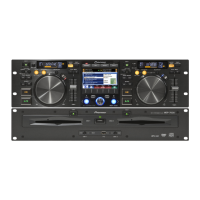
In this troubleshooting section, causes and defective points can be searched for from symptoms.
It is recommended to perform auto device diagnosis and to check the status LEDs and error codes
before disassembling the product, in order to infer failure points.
See “[3] POWER DELIVERY” in “4.3 BLOCK DIAGRAM” for details on the power supply system of each block.
For details on the waveforms whose numbers are described in this section, see “10.29 WAVEFORMS,”
where detailed information such as the points at which to measure waveforms is described
(the same waveform numbers are used in “10 SCHEMATIC DIAGRAM” and “11 PCB CONNECTION DIAGRAM”).
There are 2 play styles, according to how the product is used.
Depending on the play style, items to be checked for the control unit differ.
1. Normal Style (Control Unit + Drive Unit)
2. Manipulator Style (Control Unit + PC)
For details on the play styles, refer to the operation manual of the MEP-7000.
List of Items
[2] Problems upon startup (Normal Style) ...................................................................57
[1] Play Styles..............................................................................................................56
[3] CONTROL UNIT (Normal Style).............................................................................59
[4] CONTROL UNIT (Manipulator Style) .....................................................................65
[5] DRIVE UNIT...........................................................................................................66
[6] SRV 1/2 DRIVE ......................................................................................................72
[7] SERVICE MODE ....................................................................................................75
[8] Auto Device Diagnosis/Status LEDs.......................................................................79
[9] Error Codes ............................................................................................................83
[1] Play Styles

 Loading...