Check the LD current value in
Service mode.
For details, see “5.4 DEFECT JUDGMENT OF
THE PICKUP ASSY.”
-
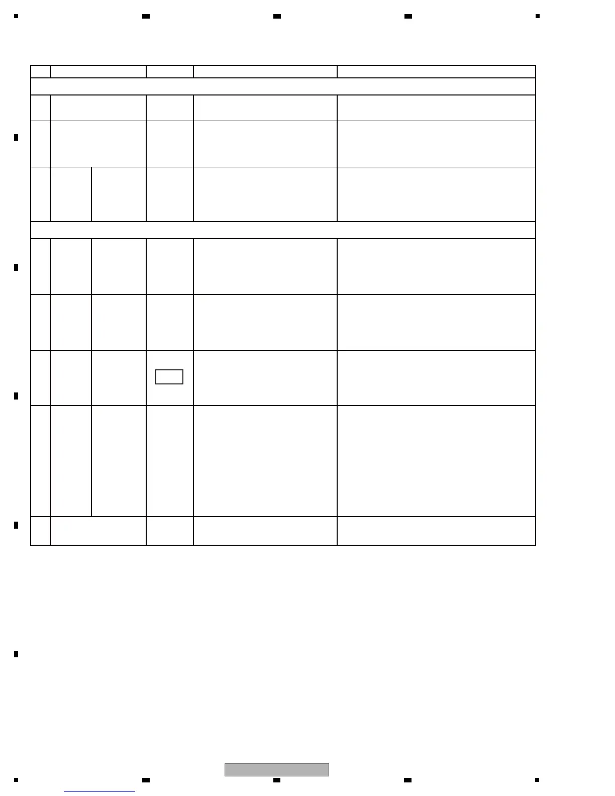
No. Waveform Items for check Causes and measuresPoints to be checked
[7-2] The drive does not operate in Test Operation mode
1-
If the problem is not resolved. The DRIVER ICs (IC100/900) are defective;
replace them.
-5-
Check if the FFC that connect the
Pickup and SRV1/2 Assys are
securely connected and if there is
breakage in the Cables.
If a connection is loose, firmly connect the
cables.
If there is breakage, replace the Cables.
-
-
2 Cable
Check the mounting status of the
following resistors :
R104-R107 (SRV 1)/R904-R907
(SRV 2) and R108-R111 (SRV
1)/R908-R911 (SRV 2).
If any resistor is improperly mounted, resolder
it.
3
SRV1/2
ASSY
-
Check that the MU1 signal
becomes H after loading is
completed.
with the
bottom
plate of the
unit
removed.
If there is no signal, check the mounting status
of the DRIVER IC and SODC (IC106/906). If
they are properly mounted, the SODC
(IC106/906) are defective; replace them.
1
SRV1/2
ASSY
-
Check if there is a PWM signal at
the center of 1.65 V of the
SPDLEC signal.
with the
bottom
plate of the
unit
removed.
If there is no signal, check the mounting status
of the DRIVER IC (IC100/900) and SODC
(IC106/906). If they are properly mounted, the
SODC (IC106/906) are defective; replace
them.
2
SRV1/2
ASSY
Check if the SPIN signal input to
Pins 29 and 26 of IC100/900 is
3.3 V at full speed.
with the
bottom
plate of the
unit
removed.
If no signal is input, check the mounting status
of R133/R933 resistors and C1160/C1960
capacitor. If they are not properly mounted,
resolder them.
3
SRV1/2
ASSY
55,56
-
Check the following voltages :
OEIC5V, VAC, VHAF, and
VLEFV.
If OEIC5V is not output, check the mounting
status of the regulator IC that regulates the
corresponding voltage and its peripheral
devices. If they are properly mounted, then the
regulator IC is defective; replace it.
Other power (VAC, VHAF, and VLEFV) is
generated at the FEP (IC102/902). If these
voltages are not output, check the mounting
status of the FEP. If they are properly
mounted, they are defective; replace them.
4
SRV1/2
ASSY
The LD does not light.
The spindle motor does not rotate.
with the
DVD/CD
drives
removed
with the
DVD/CD
drives
removed
 Loading...