Check the LD current value in
Service mode.
For details, see “5.4 DEFECT JUDGMENT OF
THE PICKUP ASSY.”
-
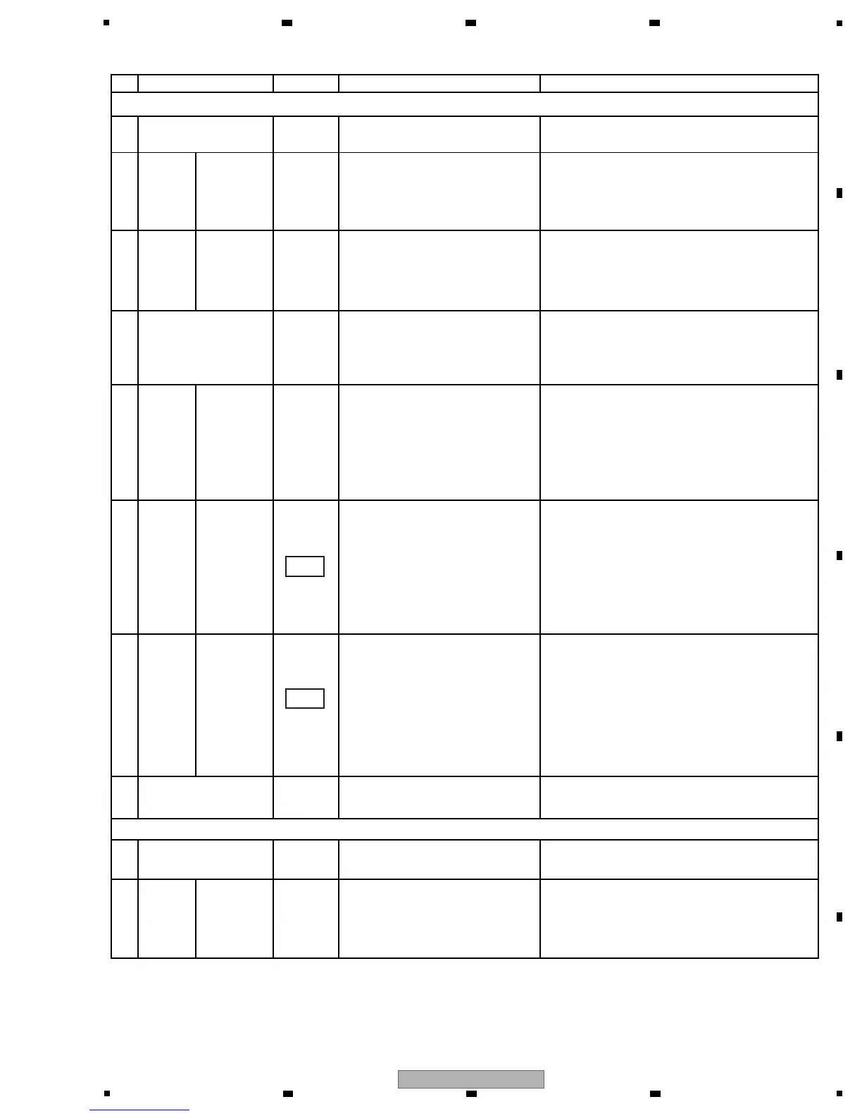
No. Waveform Items for check Causes and measuresPoints to be checked
1
4
-
Check the resistance of the
actuator.
For details, see “5.4 DEFECT JUDGMENT OF
THE PICKUP ASSY.”
-8 -
Check that the spindle motor is
rotating at 2000 rpm.(Focusing is
not possible if it is not rotating at
that speed.)
If the spindle motor is not rotating, go to “The
spindle motor does not rotate” in this section.
-
TRAVERSE
MECHANISM
-
Open the bottom plate of the
drive unit and check the following
voltages: V+8D, 6R5V, V+5SDV,
A5V, A3R3V, D1R5V
with the
bottom
plate of the
unit
removed.
If there is a power supply unit that does not
output voltage, check the mounting status of
the regulator IC and its peripheral devices. If
they are properly mounted, they are defective;
replace them.
2
SRV1/2
ASSY
-
Check that the MU1 signal
becomes H after loading is
completed.
with the
bottom
plate of the
unit
removed.
3
SRV1/2
ASSY
-
Check the SPDLFG signal (18
pulses per rotation must be
generated).
If there is an output signal, check the mounting
status of the terminals of the FEP (IC102/902).
If they are properly mounted, then they are
defective; replace them.
If no signal is output, check the mounting
status of the terminals of the SODC
(IC106/906).If they are properly mounted, then
they are defective; replace them.
5
SRV1/2
ASSY
Check the FE signal (if the
S-shaped signal is output in the
middle of FEDRV's rise after it
drops from 1.65 V).* See the
waveforms.
If the waveform of the output signal is normal,
check the mounting status of the terminals of
the SODC (IC106/906). If they are properly
mounted, go to [7].
If the waveform of the output signal is not
normal, check the mounting status of the
terminals of the FEP (IC102/902). If they are
properly mounted, they are defective; replace
them.
6
SRV1/2
ASSY
53,54
Check the FEDRV signal (1.65 V
center).
If the waveform of the output signal is normal,
check the mounting status of the terminals of
the DRIVER IC (IC100/900). If they are
properly mounted, then they are defective;
replace them.
If the waveform of the output signal is not
normal, check the mounting status of the
terminals of the SODC (IC106/906). If they are
properly mounted, they are defective; replace
them.
7
SRV1/2
ASSY
53,54
Focusing not possible
-2
Check if focus is in. (If focus is
out, tracking is not closed.)
See “Focusing not possible” in this section.
Tracking is not closed.
-1
DVD/CD DRIVES
SRV1/2
ASSY
If a CD is loaded, check the E
and F signals (signals at 2.2 V
center).
If there are not E nor F signals, check the
mounting status of CN100/900. If they are not
properly mounted, resolder them. If the
problem is not resolved, replace the Traverse
mechanism.
with the
DVD/CD
drives
removed.
with the
DVD/CD
drives
removed.
with the
DVD/CD
drives
removed.
with the
DVD/CD
drives
removed.
If there is no signal, check the mounting status
of the DRIVER IC (IC100/900) and SODC
(IC106/906). If they are properly mounted, the
SODC (IC106/906) are defective; replace
them.
 Loading...