PIPER COMANCHE SERVICE MANUAL
V - SURFACE CONTROLS 04/01/09
1G20
B. Check, and if required, adjust rudder for neutral alignment with relation to the neutral position of
the rudder pedals, and cables for correct tension as required in Table V-I. The following procedure
may be used:
1. Place airplane on jacks (refer to Jacking, Section II) to clear the nose wheel.
2. Clamp the rudder pedals to align in a lateral position as shown in Figure 5-13.
3. If not previously removed, remove the tail cone fairing by removing attaching screws.
4. Position the rudder trim in the neutral position in accordance to Paragraph 5-31.
CA
UTION: DO NOT USE A ROD LARGER THAN THE BEND RADIUS OF THE
TRAILING EDGE SO AS TO AVOID DAMAGE TO THE RUDDER.
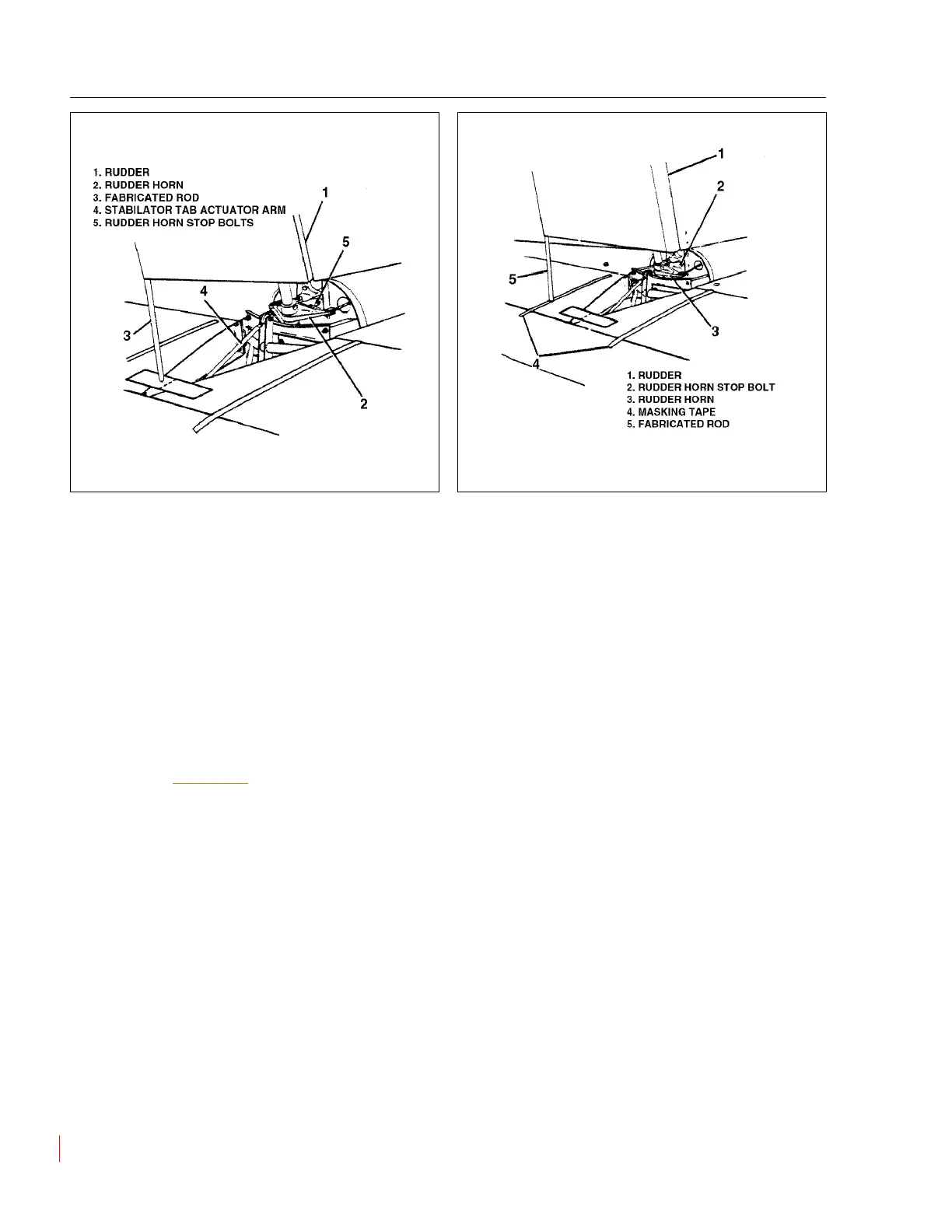
5. Insert a small diameter rod into the bottom of the rudder at the trailing edge, and allow its end
to extend down to the stabilator trim control rod. (Refer to Figure 5-10.)
6. Apply masking tape at 90° to airplane centerline, between stabilator halves immediately
beneath rod inserted on rudder. On tape, mark the airplane centerline (stabilator tab actuator
arm rod). (Refer to Figure 5-10.)
7. With the rudder pedals clamped, check that the rod in rudder aligns with the trim control rod
and cable tension is correct as required in Table V-I. (Cable tension is taken at the flexible
portion of the cable at the forward cabin bulkhead station 50.0.)
8. Should alignment and/or cable tension be incorrect adjust the turnbuckles which are attached
to the rudder pedal assembly to obtain correct alignment and tension.
9. Remove the clamps from the rudder pedals.
Figure 5-10. Determining Neutral Rudder Position
Figure 5-11. Checking Rudder Travel
 Loading...


