PIPER
COMANCHE
SERVICE
MANUAL
A
....
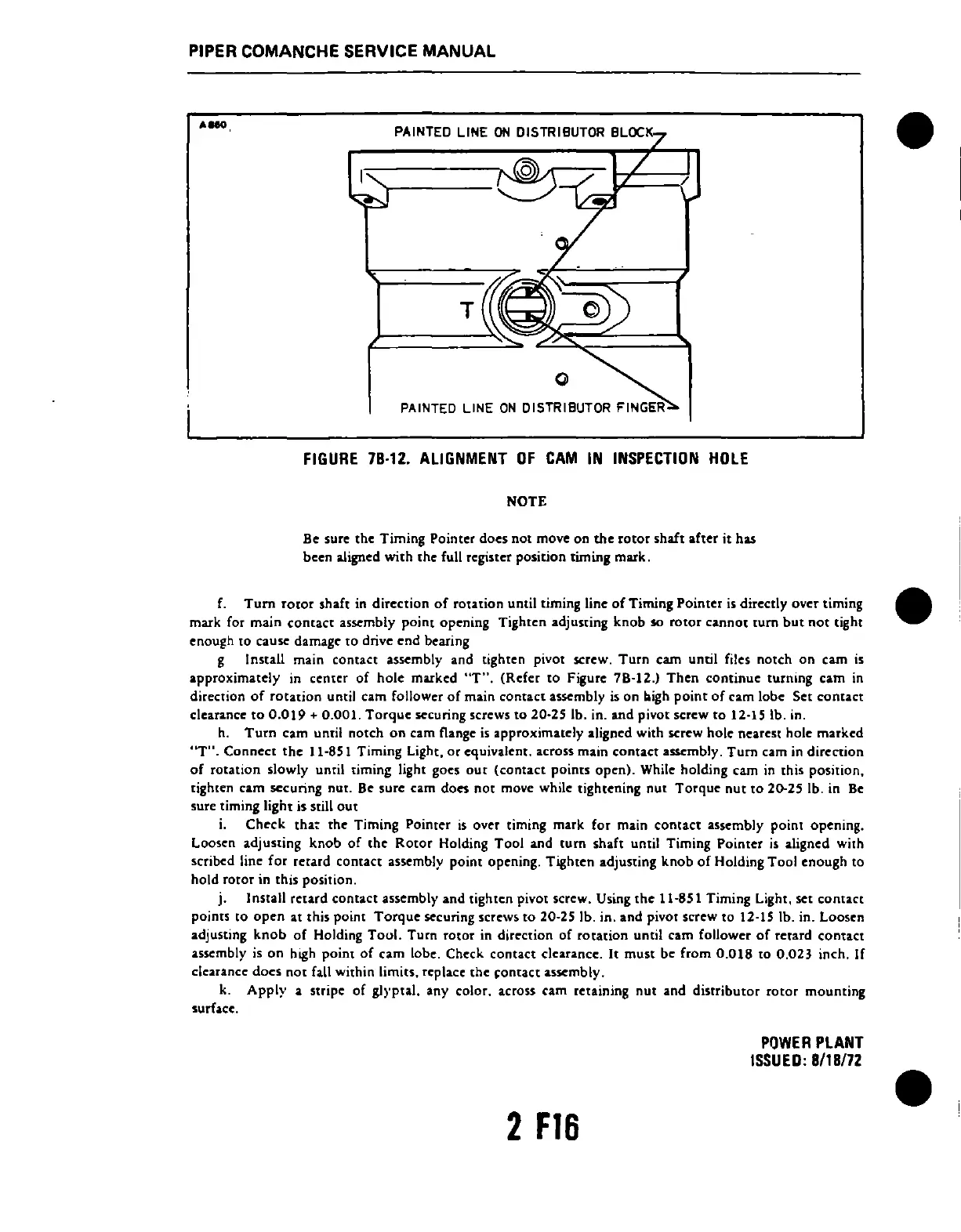
PAINTED LINE
ON
DISTRIBUTOR BLOCK
1'
......
___
_
T
PAINTED LINE
ON
DISTRIBUTOR FINGER
FIGURE
78·12.
ALIGNMENT
OF
CAM
IN
INSPECTION
HOLE
NOTE
Be
sure the Timing Pointer docs not move on the rotor shaft after it has
been aJigncd with the full registet position timing mark.
f.
Tum
rotor
shaft in direction
of
rotation until timing line
of
Timing Pointer
is
directly over timing
mark for main
contact
assembly point opening Tighten adjusting knob so
rotor
cannot
tum
but
not
tight
enough
[0
cause damage
to
drive
end
bearing
g Install main contact
assembly and tighten pivot screw.
Turn
cam until files notch on cam
is
approximately in center of hole marked
"T".
(Refer
[0
Figure 78-12.) Then continue turning cam
in
direction
of
rotation
until cam follower
of
main
contact
assembly
is
on bigh
point
of
cam lobe Set
contact
clearance
to
0.019
+ 0.001.
Torque
securing screws
to
20-25 lb. in. and pivot screw
to
12-15 lb. in.
h.
Turn
cam until notch
on
cam flange
is
approximately aligned with screw hole nearest hole matked
"Til. Connect
the
11-851 Timing Light,
or
equivalent. across main
contact
assembly.
Turn
cam in direction
of
rotation slowly until timing light goes
out
(contact
points open). While holding cam
in
this position,
tighten cam securing nut.
Be sure cam
doC'S
not
move while tightening
nut
Torque
nut
to
20-25 lb. in
Be
sure timing light is still
out
i. Check
tha~
the Timing Pointer
is
over timing mark for main
contact
assembly point opening.
loosen
adjusting
knob
of
the
Rotor
Holding Tool and
tum
shaft until Timing Pointer
is
aligned with
scribed line
for
retard contact assembly point opening. Tighten adjusting
knob
of
Holding Tool enough
to
hold rotor in this position.
j.
Install retard
contact
assembly and tighten pivot screw. Using
the
ll.fJSl
Timing Light, set
contact
points
to
open
at this point
Torque
securing screws
to
20-25 lb. in. and pivot screw
to
12-15 lb. in. Loosen
adjusting
knob
of
Holding
Tool.
Turn rotor in direction
of
rotation
until cam follower
of
retard
contact
assembly
is
on
hLgh
point
of
cam lobe. Check
contact
clearance.
It
must
be from
0.018
to
0.023 inch. If
clearance
does
not
fall within limi[S, replace
the
~ontact
a.sscrnbly.
k.
Apply
a stripe
of
glyptal. any color. across cam retaining
nut
and distributor
rotor
mounting
surface.
2
F16
POWER
PLANT
ISSUED:
8118172
 Loading...


