. ,
PIPER
COMANCHE
SERVICE
MANUAL
' .
.....
AOJUIT
IW,
.ell""
5
••
L.CU:"
",UT
••
'OWTltOL.
&JIM
4 • COIITIIOL.
willI",
••
ICItIW
a"I"I
.. f
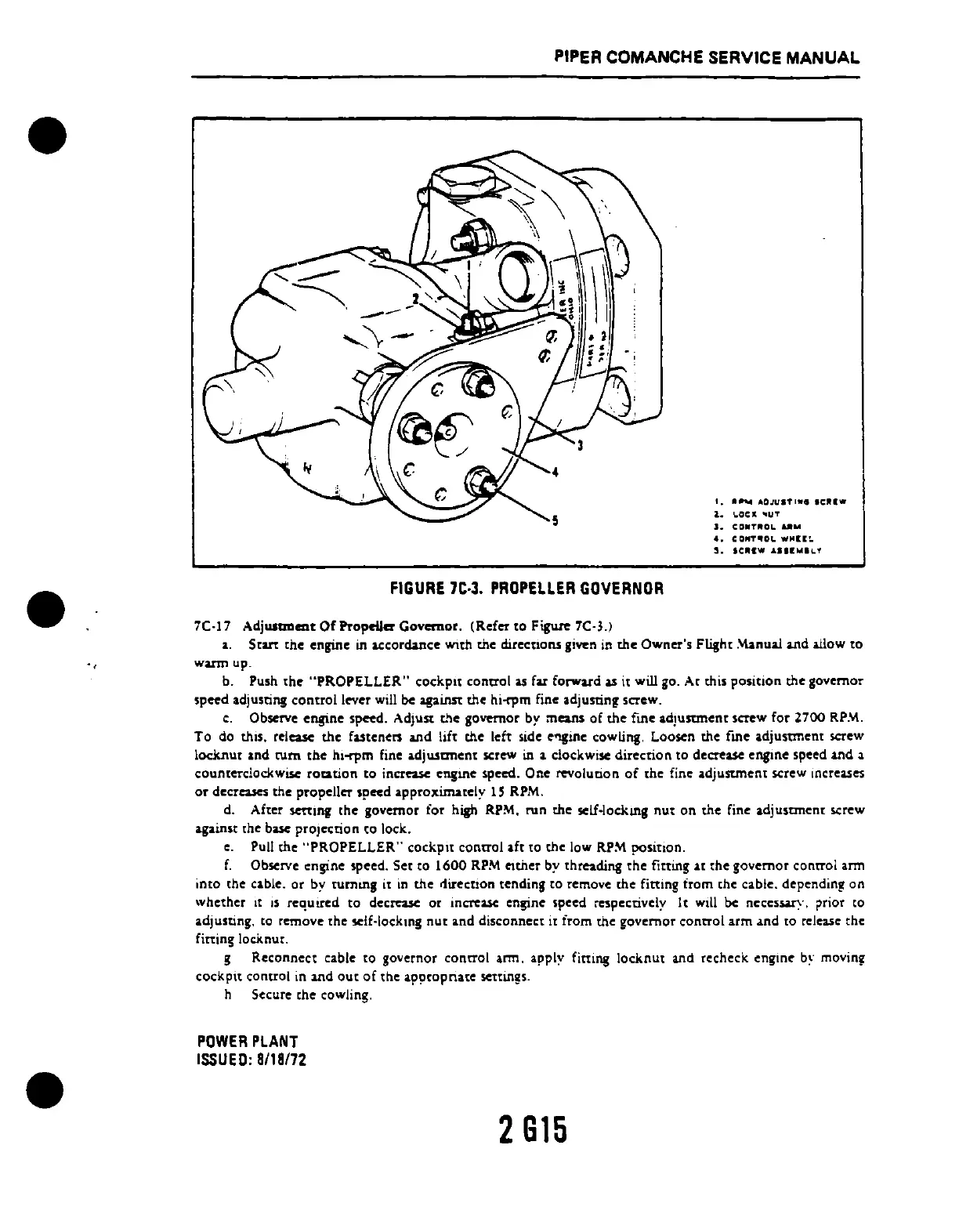
FIGURE
'C·3.
PROPELLER
GOVERNOR
7C·17
Adj....",ent
Of
Propeller Governor.
(R.fer
to Figure 7C·l.)
a.
Srut
the
engine in I.Ccorda.ncc WIth
the
directiOns given in
the
Owner's
Flight .\'\anual
and
allow
to
warm up .
b.
Push the "PROPELLER" cockpit control
as
far forward
as
it will
go.
At this position the gov.rnor
speed adjusting control lever
will
be
against the hi-rpm fine adjusting screw.
c.
Observe
.ngin.
sp~d.
AdjUst t!l. governor by means of the
fin.
adJustm.nt screw for 2700
RP.'.\.
To
do
thiS.
release the fastenen and
lift
the left side
c1't!inc
cowlinl. Loosen the fme adjustment screw
lock.nut and
tum
tbe hl-rpm fine adjustment screw in a clockwise direction to decrease engine speed and a
counterclockwise
roation
to
increase
cng1!lC
speed. One revalueon
of
the fine adjuStment screw Increases
or
d.cr
....
s the prop.ller
sp~d
approximat.ly
15
RPM.
d. After
sen:Ul,
the
governor for high RPM. run
the
self·lockUlJ
nut
on
the
fine adjusoncnr screw
against the base projection
co
lock.
•. Pull the ··PROPELLER··
cockpn
control aft to the low
RP~
position.
f.
Observe engine speed.
Sec
to
1600
RPM
ather
by chreading the
fitting
at the governor concroi arm
into the cable. or
by turnlllg it
in
the rfirection tending to remove the fitting from the cable. depending on
whether
It
IS
requlred to decrease or
mcrca.se
engine speed respectively
It
will
be
ncccssuy. !,rior
co
adjusting.
to
remove the
~if~locklOg
nut
and disconnect it from the governor concrol arm .lnd to release the
fitting locknut.
g Reconnect cable to governor concrol arm. apply fitting locknut and recheck
engmc
b~'
movlO,
cockpit
control in 1l\d
out
of
the appropriate sen:in!s.
h Secure the cowling.
POWER
PLANT
ISSUED:
8/18172
2815
 Loading...


