PIPER
COMANCHE
SERVICE
MANUAL
7
10
12
5
8
2
'~
?j
I I
I 8
8
4
2
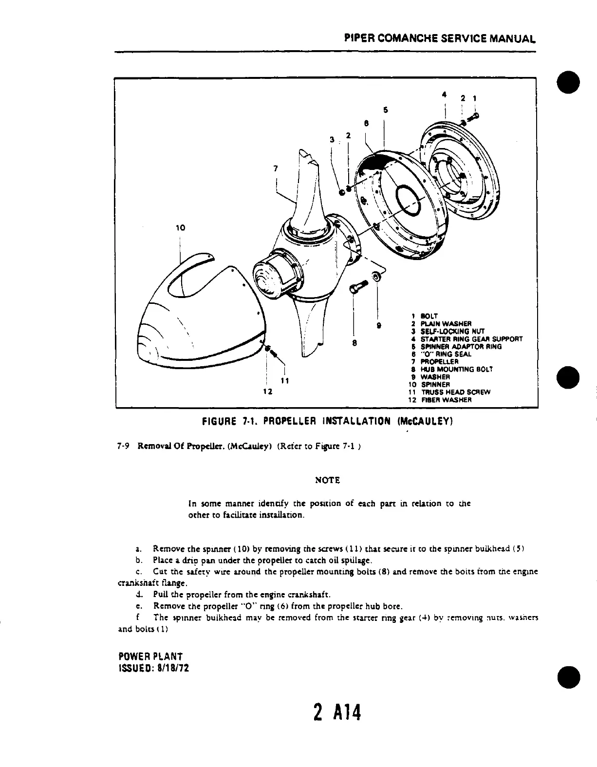
1 BOLT
2 PLAIN WASHER
3
SELf-LOCKING
NUT
"'
STARTER
RING
GEAR
SUPPORT
5
SPINNER
ADAPTOR
RING
6 --0-- RING SEAl.
7 PROPELlER
8 HUB MOUNTING
BOLT
9 WASHER
10
SPlHNER
11
TRUSS HEAD
SCREW
12
FIBER
WASHER
FIGURE
7-1.
PROPELLER
INSTALLATION
(McCAULEY)
7-9 Removal
Of
PropeUer_
(McUwey)
(Reier to Figure
7-1
)
NOTE
In some manner identify the position
of
each
put
in relation to the
other
to facilitate installation.
a.
Remove
the
Sp1lU1CT (10) by removing the screws (11) that secure it
[0
the spinner bulkhead (5)
b.
PlAce.
dri? pUl under the propeUer to
c.tch
oil .pillage.
c.
Cut
the
safety
wU'c
around the propeller
mounting
bolts (8)
~d
remove the bolts tram tile engme
<fUlks;'.!t t1Ulge.
-i. Pull the propeller from the engine cr.nl<sh.ft.
e. Remove
the
propeller
"0"
nng
(6)
from the propeller hub
bore_
f The spmnc!
bulkhnd
may be remo\'cd from the startcr ring
icar
(4) by :-emovmg :lues. wasners
and bolts (
1)
POWER
PLANT
ISSUED:
8/18/72
2
A14
•
•
 Loading...


