EasyManua.ls Logo

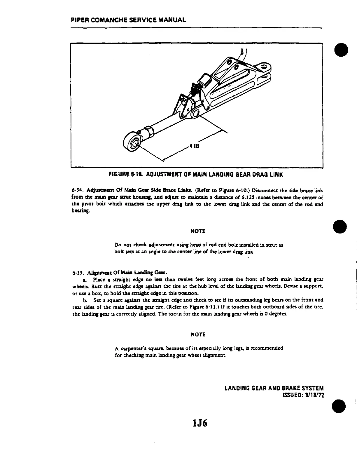
Piper Comanche PA-24 - FIGURE 6-10. ADJUSTMENT OF MAIN LANDING GEAR DRAG LINK; 6-34. ADJUSTMENT OF MAIN GEAR SIDE BRACE LINKS; 6-35. ALIGNMENT OF MAIN LANDING GEAR

Piper Comanche PA-24
846 pages
Print Icon
To Next Page IconTo Next Page
To Previous Page IconTo Previous Page
Loading...
PIPER COMANCHE SERVICE
MANUAL
FIGURE
&-10.
ADJUSTMENT
OF
MAIN
LANDING
GEAR
ORAG
LINK
6-34. Adj
..........
Of MUa
~
Side
Brut
Liala.
(Refer.o
PiIWe
6-10.) Disconllec:t
the
,ide braee link
from
the
main
p<
sau.
bousius
....
eI
acljUit
to
maintain • clilwlce
of
6.12'
inches between
the
c
...
tel
of
tbe
pivo.
bolt
whicb
.tuebcs
the
upper
cInt
link
to
the
lower
cInt
link
...
eI
the
cen.er
of
the
roc!
enel
bcarinJ·
NOTE
Do
no.
check
.eljusanent
usin,
be&cl
of
roc!
enel
bolt
inst&1Ieel
in
saul
..
bal.
sea
.....
a.ng1e
to
the
center
line
of
the lower
elnslink.
6-35.
Alipmcnt
Of
MUa LaDdiDI
Gar.
&.
Place
.......
ht
eels<
no
less tbUI twelve feet Ions
.cross
the
front
of
both
main
l&ncIing
gear
wheels.
Bu"
the straigh.
eels<
&pins<
'he
tire
&!
the
hub level
of
the
lancling
gear
wheels.
Devise
•
suppa".
or
usc • box.
'0
holel
the
straigh. eelse in this position.
b.
Set.
square &pins<
the
......
h.
eclse
&Del
check
,0
sec
il
its
ou
......
elins 1
..
bears
on the
fran
••
nd
rcar sides of
the
main landins
gear
tire. (Refer
'0
Fisure 6-11.) If
i.
,ouches both
ou,board
sides
of
the tire.
,he
Ilndins
gear is correctly
alisncd.
The
,o"';n
for
'he
main laneling gear wheels
is
0 d
.......
NOTE
A
carpenter',
square. bec.usc
of
its especwly Ions 1
....
is
recommended
for
checkins main landins gear wheel alignment.
IJ6
LANDING
GEAR
AND
BRAKE
SYSTEM
ISSUED:
8/1
Bn2

Table of Contents