e'-
PIPER
COMANCHE
SERVICE
MANUAL.
9-58.
R.,.I
...
,.
(D.I
...
R • ...,)
9-59.
o..ckin,
R
..
ulotor Circuit. Altemator failures
may
be
caused
by
circuit
misconnections,
.lICh
..
reversed l
..
d.
or Iborted
0'
I'oaadial
of
te
...
iaals
witb a
."",...mve,.
etc.
The
(ollowinC
pfovid
•••
meanl
of
loeatitle
ci.rcuit miscOCUleeticaL It .110
covers
the
different
typeS
of
repletor
panel
board
circuit
trace
defects
which iAdicate •
certain
type of
_iring
hame.1
milCODftecuonl.
A bumed
circuit
:race
on the regulator panel board
is
proof
that
a
circuit
milconnKtion
.~l.ts,
or
oecuned
at some time. However. a miaconaectioa will aot
al_ays
callS
••
bumed. Circuit
trac.
even thoulh
circuit
component failure.
hive
been
cauaed..
Before
installiDl
a
n.ew
regulator,
it
is
very import8IJt
to
make aure
that
no
wirinC
circuit
defects
or
wirial
bamess
milconnectiOft.l
exilt.
U the
.iria.
ham
...
is
defective,
or
if
milcon-
nections
eKist.
tbe
ne
..
regulato, ...
ill
fail too.
Futh
....
ore.
repeated
replae.ment
of
,",wators
will aaly result in repeated regulator
failwes.
ed
this
will
continue
until the
circuit
defect
is
corrected.
To
check
the
wiring
harnesl
for
defects
or miscon.nection. before iDStallin, the new regu-
lato,.
observe the
followinl
procedure.
MOTE
Meter connections
are
lIlade to the ham
••
s
connector
that
has
been
unplulled
from
the reaulato,.
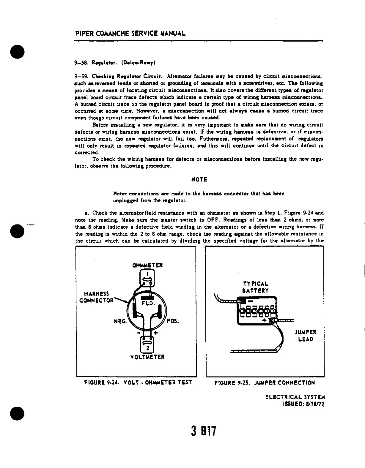
a. Check the
IItemator
field
resisteee
with lID. ohmmeter
a.
shown in Step 1.
Figure
9-24 and
note the
,eadin,.
Make
.....
the
mute,
.... iteb
is
OFF.
R
..
diaKs of
lell
tbOll
2 obm
••
0'
IDo,e
than 8 ohms indicate a defec:tive field windina in the
altemator
or a defective winn&
harness.
If
the read.ing is Within the 2 to 8
ohm
range.
check
the readina
against
the
aUo.able
resisumce
in
the Circuit which
can
be
calculated
by
dividina
the
specified
voltage
for
the
altemator
by
the
HARHESS
COMMECTOR
OHMMETER
VOLTMETER
POS.
FIGURE
9.2
•.
VOLT·
OHMMETER
TEST
TYPICAL
BATTERY
JUMPER
LEAD
FIGURE
9.25.
JUIoIPER
COMMECTIOH
ELECTRICAL
SYSTEM
ISSUED:
8118m
3817










 To Next Page