\
PWERCO~CHESER~CE~AL
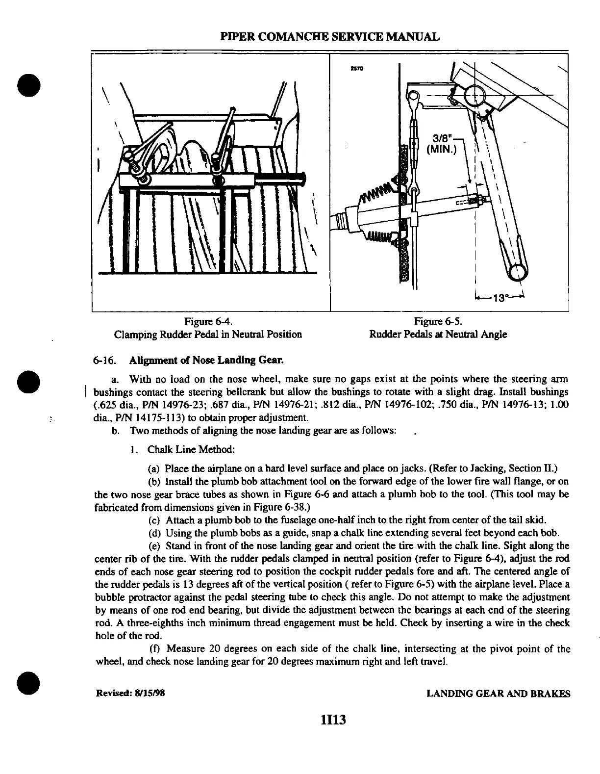
Figure 6-4.
Clamping Rudder
Pedal in Neutral Position
I'
\
,
\
....
3/8"
(MIN.\!
Figure 6-5.
I
I
I
I
I
I
L
13
o..-o1
Rudder Pedals at Neutral Angle
6-16.
Alignment
of
Nose Landing Gear.
a. With no load on the nose wheel, make sure no gaps exist
at
the points where the steering arm
bushings contact the steering bellcrank but allow the bushings to rotate with a slight drag. Install bushings
(.625 dia.,
PIN 14976-23; .687 dia., PIN 14976-21; .812 dia., PIN 14976-102; .750 dia., PIN 14976-13; 1.00
dia., PIN 14175-113) to obtain proper adjustment.
b. Two methods
of
aligning the nose landing gear are as follows:
1.
Chalk Line Method:
(a)
Place the airplane on a hard level surface and place on jacks. (Refer to Jacking, Section
n.)
(b) Install the plumb bob attachment tool on the forward edge
of
the lower fire wall flange,
or
on
the two nose gear brace tubes as shown in Figure 6-6 and attach a plumb bob to the tool. (This tool may be
fabricated from dimensions given in Figure 6-38.)
(c) Attach a plumb bob to the fuselage one-half inch to the right from center
of
the tail skid.
(d) Using the plumb bobs as a guide, snap a chalk line extending several feet beyond each bob.
(e) Stand in front
of
the nose landing gear and orient the tire with the chalk line. Sight along the
center rib
of
the tire. With the rudder pedals clamped in neutral position (refer to Figure 6-4), adjust the rod
ends
of
each nose
gear
steering rod to position the cockpit rudder pedals fore and aft. The centered angle
of
the rudder pedals is 13 degrees aft
of
the vertical position ( refer
to
Figure 6-5) with the airplane level. Place a
bubble protractor against the pedal steering tube to check this angle.
Do
not attempt to make the adjustment
by means
of
one rod end bearing. but divide the adjustment between the bearings at each end
of
the steering
rod. A three-eighths inch minimum thread engagement must be held. Check by inserting a wire in the check
hole
of
the rod.
(f)
Measure
20
degrees on each side
of
the chalk line, intersecting at the pivot point
of
the
wheel, and check nose landing gear for
20
degrees maximum right and left travel.
Revised:
8115198
LANDING
GEAR
AND BRAKES
1113