PIPER
COMANCHE
SERVICE
MANUAL
-
I.
00011
'TO~
1.11111
1.
MauMT'."
....
CIlIT
AI""'''''!''
3.
140P..O
oow
.....
1'
••
••
ACTUATe:.
"UTI
••
'ALL
JOINT
••
"enACT
10_
JlOo
T.
U_'_
........
oun
I.
'.ANI
.U
.....
T
••
.,oa.
MI
....
1"'
....
''''"''001
I
••
00_
1
....
·14
...
001
II.
DOCM
",
••
t
......
I~
..
OI
8
I
••
I"'"
fI.N
"'.-14-1101
II.
QOOll
{
.....
a.·1101
9
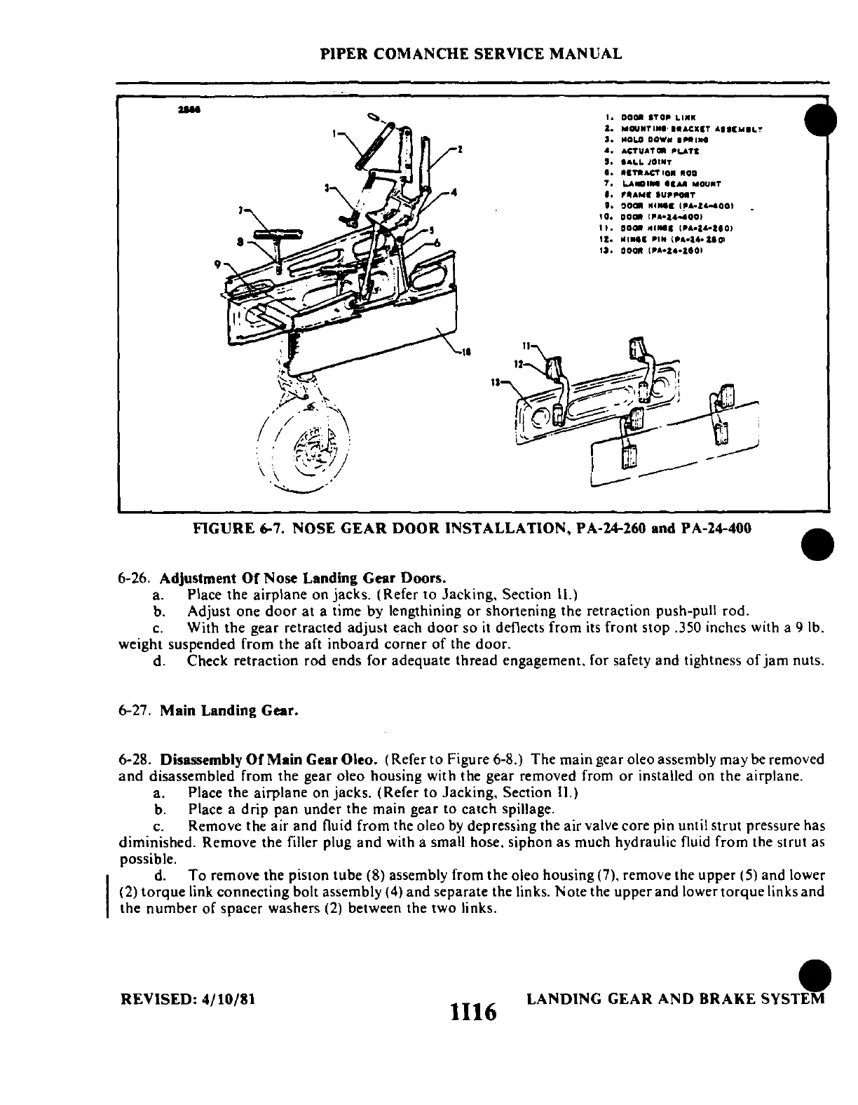
FIGURE
6-7. NOSE
GEAR
DOOR
INSTALLATION, PA·24-260 and PA·24·400
6·26.
Adjustment
Of
Nose Landing Gear Doors.
a. Place the airplane on jacks. (Refer to Jacking. Section ll.)
b. Adjust one
door
at a time by lengthining or shortening the retraction push·pull rod.
c.
With the gear retracted adjust each door so
it
deflects from its front stop .350 inches with a 9 lb.
weight suspended from the aft inboard corner of the door.
d. Check retraction rod ends for adequate thread engagement. for safety and tightness
of
jam
nuts.
6-27.
Main
Landing Gear.
6·28. Disassembly
Of
Main Gear Oleo. (Refer to Figure 6·8.) The main gear oleo assembly may be removed
and
disassembled from the gear oleo housing with the gear removed from or installed on the airplane.
a. Place the airplane on jacks. (Refer to Jacking. Section II.)
b.
Place a drip pan under the main gear to catch spillage.
c.
Remove the air and fluid from the oleo
by
depressing the air valve core pin until strut pressure has
diminished. Remove the filler plug
and
with a small hose. siphon as much hydraulic fluid from the strut as
possible.
d.
To remove the piston tube (8) assembly from the oleo housing (7), remove the upper (5) and lower
(2)
torque
link connecting bolt assembly (4) and separate the links. Note the upper and lower torque links and
the number of spacer washers
(2)
between the two links.
e
REVISED:
4/10/81
1116
LANDING GEAR
AND
BRAKE
SYSTEM
 Loading...


