PIPER COMANCHE SERVICE MANUAL
04/01/09 V - SURFACE CONTROLS
1H4C
5-38. Installation of Stabilator Trim Mechanism. (Refer to Figure 5-14.)
A. To install the stabilator trim mechanism, assemble the drum assembly (10) onto its support brackets.
Attach the bellcrank (34) to the bearing blocks and safety. Draw the rim cables (2) into the fuselage,
allowing them not to cross, and install the cable pulleys.
B. The forward trim cable may be installed by drawing the cable to the location of the trim crank
pulley (1) and idler pulley. Wrap the cable around the crank pulley, then to the idler pulley and back
to the crank pulley. Continue the cable to the aft section and install cable pulleys that were removed.
C. To rig and adjust the trim mechanism and cables, refer to Paragraph 5-39.
5-39. Rigging And Adjustment Of Stabilator Trim Mechanism.
CA
UTION: VERIFY FREE AND CORRECT MOVEMENT OF STABILATOR TAB. WHILE IT
WOULD SEEM SELF-EVIDENT, FIELD EXPERIENCE HAS SHOWN THAT THIS
CHECK IS FREQUENTLY MISINTERPRETED OR NOT PERFORMED AT ALL.
ACCORDINGLY, UPON COMPLETION OF STABILATOR TRIM RIGGING AND
ADJUSTMENT, VERIFY THAT THE STABILATOR TAB MOVES UP WHEN THE
TRIM WHEEL IS TRIMMED DOWN; AND, THAT THE STABILATOR TAB MOVES
DOWN WHEN THE TRIM WHEEL IS TRIMMED UP.
A. To rig the stabilator trim system, draw the trim cable, rotating the cable drum until approximately 7
wraps (PA-24-180, PA-24-250 and PA-24-260) or 8 wraps (PA-24-400) remain on the drum of the
top series of wraps.
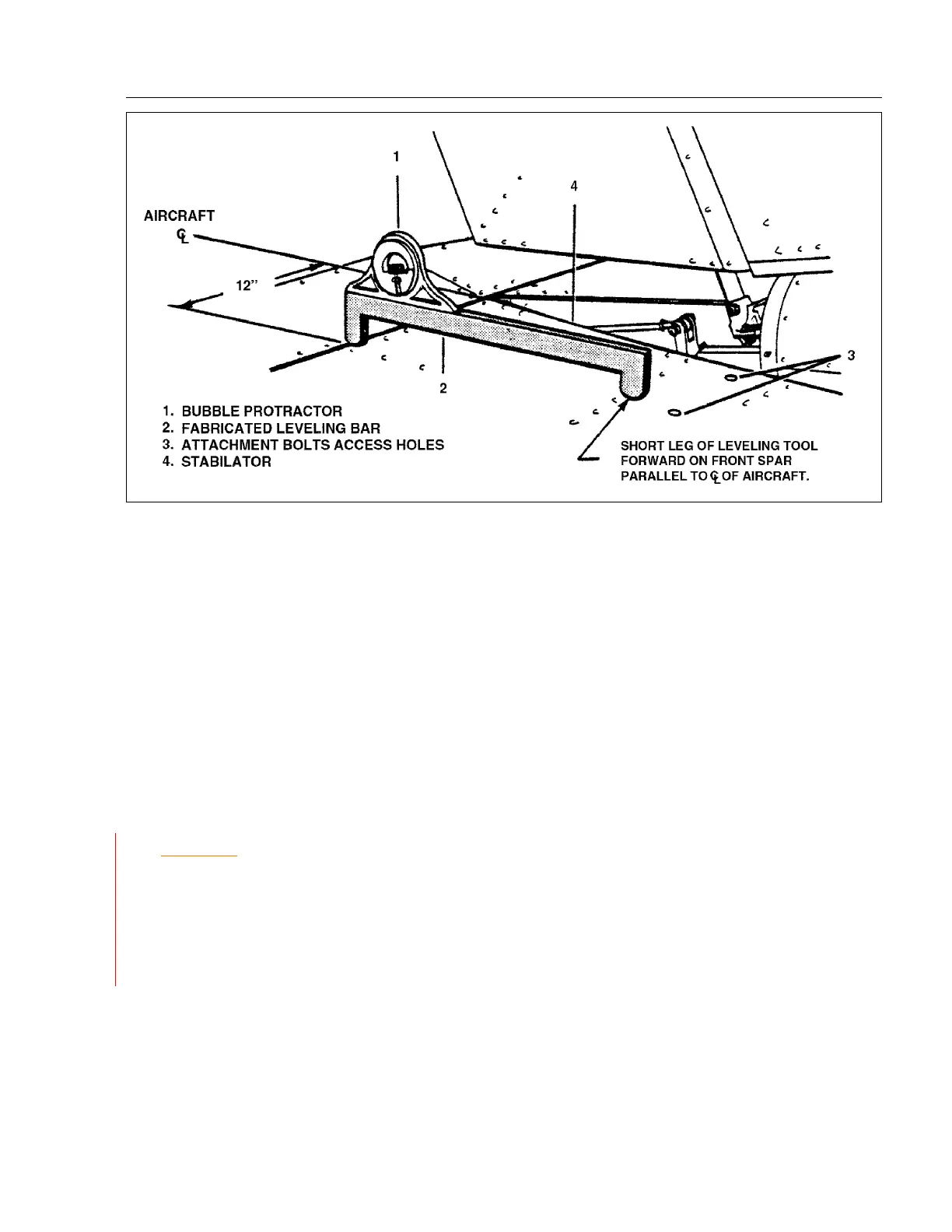
Figure 5-15. Checking Stabilator Travel.
 Loading...


