..
I
..
•
.,.
..
..
"
"
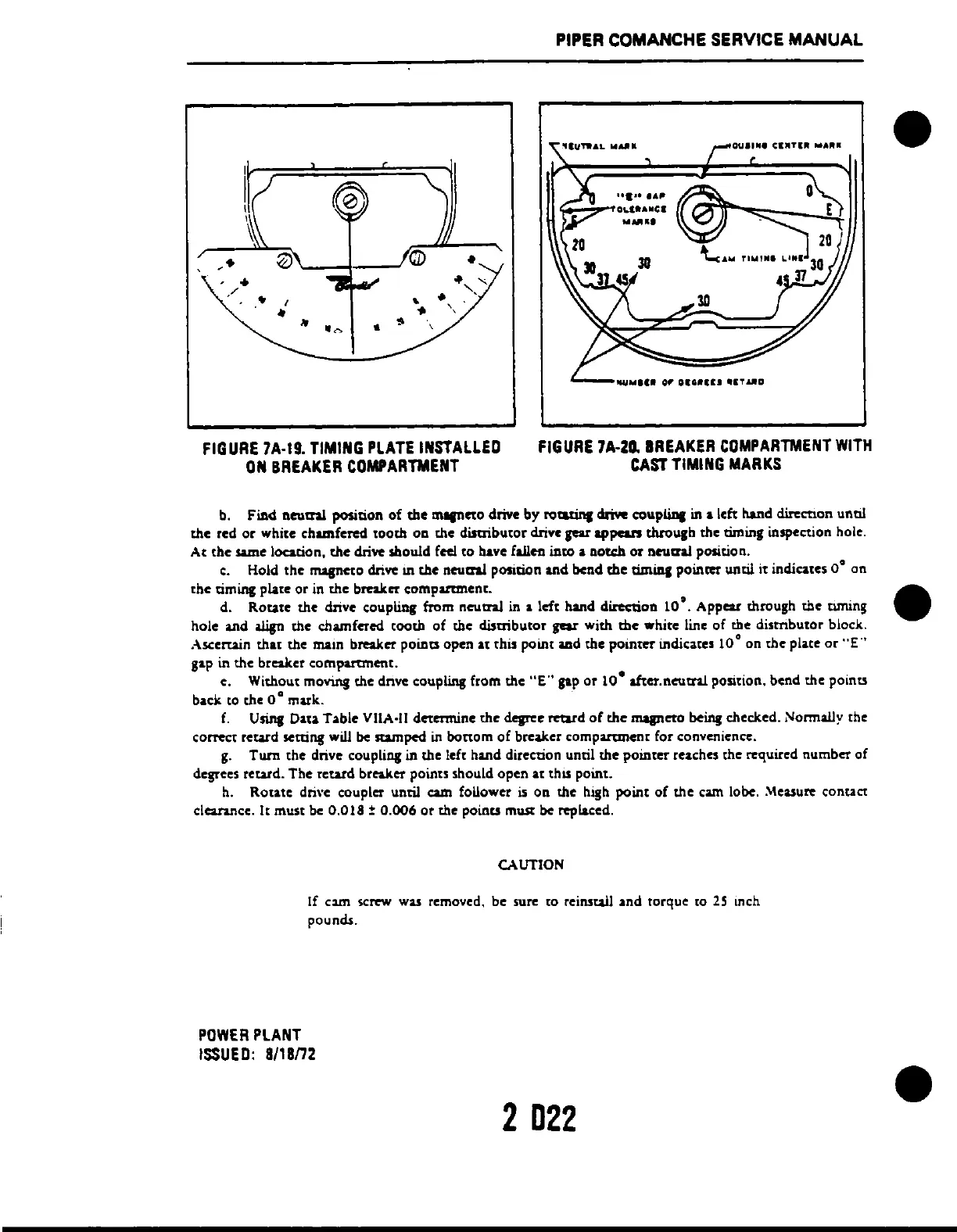
FIGURE
7A-19_
TIMING
PLATE
INSTALLED
ON
BREAKER
COMPARTMENT
PIPER COMANCHE SERVICE
MANUAL
......
A~
.;;;;...:;,...,OI.I
...
IIICI
"UIUI
FIGURE
7A-za.
BREAKER
COMPARTMENT
WITH
CAST
TIMING
MARKS
b. Find
nlNtni
position
of
the
m
....
cto drive by
rowinl
cIriYe
couplinl
in
a left lland dirccnon unc.!
the
red
or
white chamfered tooth on the
disaibutor
drive
gear
appears through the timing inspection hole.
At
the same location,
the
dri
..
should feci
to
bave fall
...
ineo
a notch or neutral position.
c.
Hold the
mqneto
dri
..
111
the
neutral position and bend
the
cimini
poinm
until it indicates
O·
on
the
timing plate or
in
the breakct compartment. _
d. Rotate the drive coupling ftom
neutnl
in
a left hand direction
10·.
Appear through
the
tuning _
hole and iIign the chamfered tooth
of
the distributor
gear
with
the
white line of the
dismbutor
block.
Ascertain
that
the
maIn breaker poiDa
open
at
this
POUlE
md
the
pOinter' indica.tes 10
0
on
the
place
or
"E"
gap in the breaker compartment.
e, Without moving the dnvc coupling from the
"E"
gap
or
10·
after.neutnl
position, bend the points
ba.ck
to the 0
0
mark.
f.
Using Data Table VilA-II dctcnnine the degree
rcurd
of
the
mqnctO
being checked. Normally the
correct retard setting will
be
lUmped in bottom
of
breaker
companmenr
for convenience.
g.
Tum
the drive coupling in the left hand direction unril the poinrer reaches the required number of
degeccs
rewd,
The retard breaker points should open at
thIS
point.
h.
Rotate dri\'c coupler until cam foUower
is
on the high point
of
the cam lobe
..
\teasu~
canuct
clearance. It must be
0.018
:
0.006
or
the points m ..... be replaced.
CAUTION
If
C2l11
screw
wa.s
removed. be sure to reinstall and torque to
25
Inch
pounds.
POWER
PLANT
ISSUED:
8118n2
2
D22
 Loading...


