•
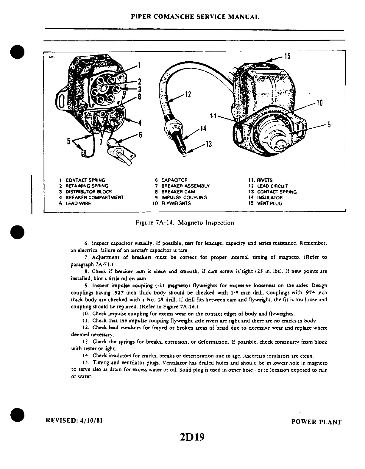
1 CONTACT SPRING
2 RETAINING SPRING
3 DISTRIBUTOR BLOCK
4 BREAKER COMPARTMENT
5 LEAD WIRE
PIPER
COMANCHE
SERVICE
MANUAL
6 CAPACITOR
7 BREAKER ASSEMBLY
8 BREAKER
CAM
9 IMPULSE COUPLING
1 0 FLYWEIGHTS
Figure 7A-14.
Magneto
Inspection
11.
RIVETS
12 LEAD CIRCUIT
13 CONTACT SPRING
14
INSULATOR
15
VENT PLUG
6.
Inspect capacitor visually. If possible. test for leak
....
capaciry and series resistance. Remember.
an
electrical
failure
of
an
airaaft
ca.pacitor
IS
rare.
7. Adjumnent
of
break
...
must be correct for
prop.,
internal timing
of
magneto.
(Ref.,
to
paragraph 7A·71.1
8. Check if breaker cam
is
clean and smooth.
if
cam screw
i'tigh[
(lS
Ill.
Ib,). If new
POIllU
are
installed. blo[
a linle oil on cam.
9.
Inspect impw.e coupling
(·21
mapeto)
flyweighu for excessi
..
loosene
..
on the axles. Design
couplings
havuig
.927 inch thick body should
be
checked with
118
inch drill. Coupling. with .974
Illch
thick body ate checked
With
a No. 18 dnll. If drill
fiu
betWeen cam and flyweight. the fit
is
[00
loose and
coupling should
be
replaced. (Refer
[0
Figure
7A·16.)
10. Check ""pulse coupling for excess wear on the
COntact
edges
of
body and flyweights.
11.
Check
th"
the ""pulse coupling flyweight
uJe
nvo"
....
[igh[ and there
ate
no
cracks
in
body
12. Check lead conduits for frayed or broken areas
of
braid due
to
excessive wear
and
replace where
deemed necessary.
13. Check the springs for breaks. corrosion.
or
defonnation. If possible. check continuiry from block
with
[ester or
Iigh
[.
14.
Check
insulato"
for
cracks.
brca.ks
or
deterioranon
due
to
age
..
-UCcrtaJn
insulators
are
clean.
1
S.
Timing
and
ventilator plugs. Ventilaror has drilled holes
and
shouid
be
In
lowest hole
in
magneto
to serve also
IS
d.ra.tn
for excess water
or
oil. Solid plug
is
used
in
other hoie .
or
in
location exposed to
rain
or
water.
9
REVISED:
4/10/81
POWER
PLANT
2D19
 Loading...


