EasyManuals Logo

Piper Comanche PA-24 User Manual

Piper Comanche PA-24
846 pages
To Next Page IconTo Next Page
To Previous Page IconTo Previous Page
Page #651 background imageLoading...
Page #651 background image
PIPER
COMANCHE
SERVICE
MANUAL
TABLE VIO-OI. PUMP PRESSURES (FUEL INJECTION)
En,in_
1~
•
.o.·N
lo-nO-A
At inlet
to
eD&me
driven
pump.
Electric
pump
on
(14 voltS)
+35
psi
(max:)
<-40
psi
(max.)
Electric
pum
p off
·2
psi
(min.)
-4 psi
(min.)
At
inlet
to
injector
Electric
pump off 14
psi
to 45
psi
18
psi
to
40
psi
(Operatinl
ranp)
U pili
miD.
for
idle
&-32.
En,in.
Prim_, Syst.",
(C.,bu,.tor
Induction).
The
eDline
primer
system
consists
,:,'
band
operated
primer pump,
supply
IiJ1es
ODd
primer
jets.
Fuel
for
the
primiDI
system
is
taken
iram
the
main fuel
lin
at
the
fuel
strainer
on
early
models
or
the
fuel
line
between
the
fuel
strainer
aDd
electric
fuel pump on
later
models.
Fuel
is
directed
thraup
the
pump.
supply
lines
and
OD
to
tbe
jets
located
at
the
induction
port
of
all
cylinders,
e:lcept
the
left
rear.
MaUlteDance
to
the
system
is
WlnecesSary.
except
at
ealiDe
overballl or when
irrelUlu
start.ing
is
eacOW1tered, caused by
one
a more
jets
beinl
plulled
aDd/or
the
primer pump
is
dirty or
leaking.
&-33. P,;
...
Pump.
a.
To
check
the
flow of
the
pump,
disconnect
the
supply
liDe within
the
engine
compartment
where the
line
divides
to go to
the
left
..,d
ript
cylinders.
Operate
the pump,
sufficient
fuel
should
flow
to
supply
all
jets
and
is
determined only
by
the
amount of
pressure
exerted
on the
pump knob.
When
operatinl
the
knob,
cbeck
for
Ie
ak",e
around
the
pis
ton.
b.
The
pump
should
be
removed from
the
aircraft
for
servicing.
This
is
accomplished
by
discannectinl
the
supply
liDes
at
the
pump.
~oosing
the
lock
....
ut
from beh.lnd the
panel.
turning off the
face
nut, Withdrawing
the
piston
from the pump body and removing the pump
from the panel.
c.
Further
disassemble
the pump and
clean
with
solvent
to remove built up foreign
de-
posits.
Ascert3!n
that
the two
check
balls
are
fr~e
to
operate
a..,'!i
seat
properly.
Replace
the
piston
"0"
rings and
lubricate
with
motor oil
before
inserting
into
pump body. If
excess
pump wear
is
indicated,
replace.
d,
To
check
the
pump
operation
before re-
installing,
assemble,
immerse
in
gasoline
and
pum
p
several
times
to
ascertain
Fl'0per oper-
ation.
FUEL
SYSTEM
2J15
3
4
2
13
1.
,"'E,I(
'&4-4-
Z.
'.U.4-
Sil'~'NG
5
12
11
:I
••
'''''''101'''
""E'","
6.
""4-ING
S."'NG
5
7
8
10
!.
STO~
.'101
11.
*,.'",E"
",
~].
9
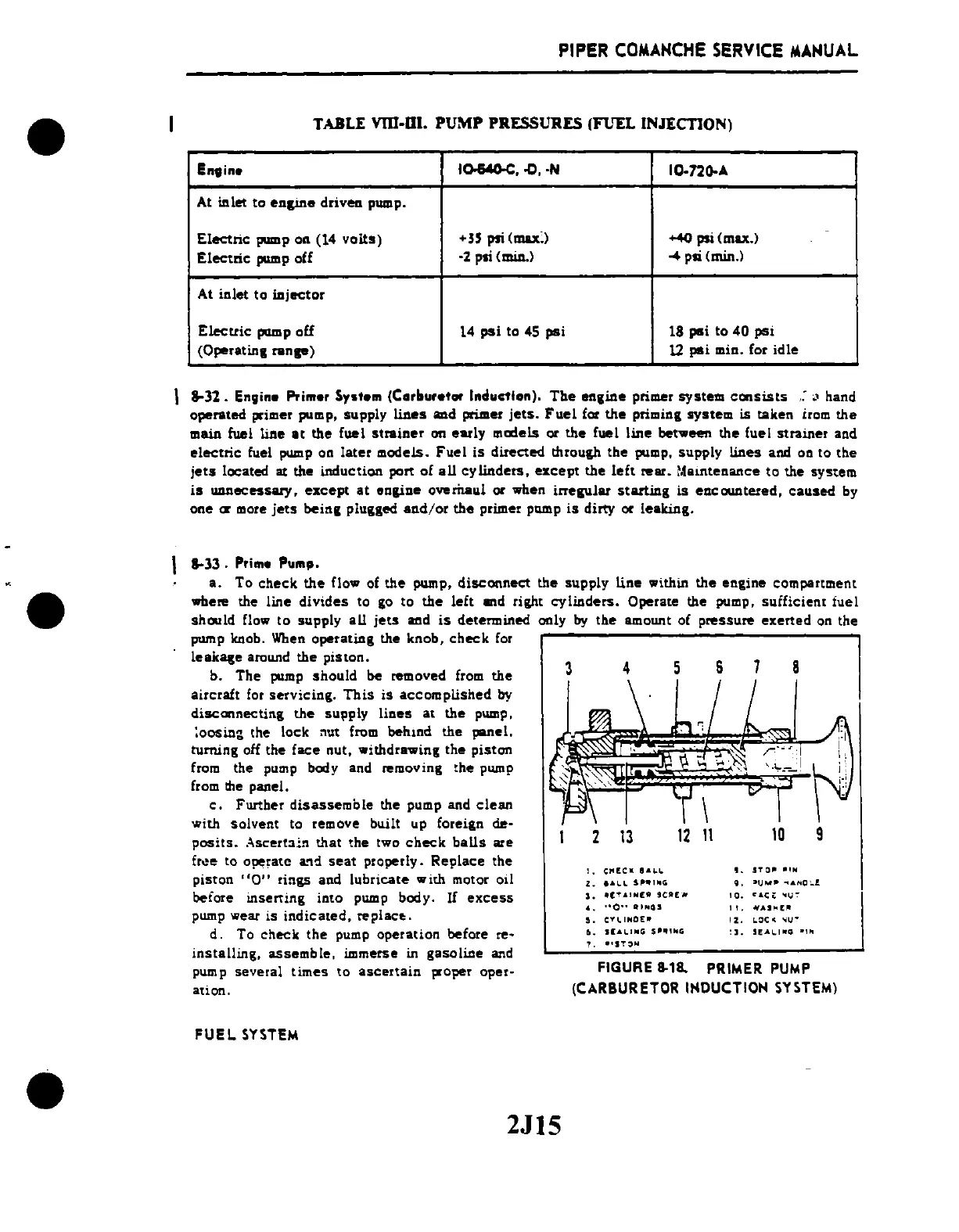
FIGURE
8-18.
PRIMER
PUMP
(CARBURETOR INDUCTION SYSTEM)

Table of Contents

Questions and Answers:

Question and Answer IconNeed help?

Do you have a question about the Piper Comanche PA-24 and is the answer not in the manual?

Piper Comanche PA-24 Specifications

General IconGeneral
ManufacturerPiper Aircraft
ModelComanche PA-24
TypeLight aircraft
First FlightMay 24, 1956
Number Built4, 857
Seating Capacity4
EngineLycoming O-360
Wingspan36 ft (11 m)
Length24 ft 8 in (7.5 m)
Stall Speed62 mph (100 km/h, 54 kn)
Height7 ft 6 in (2.3 m)

Related product manuals