'.;-
PIPER
COMANCHE
SERVICE
MANUAL
I.
!.oOC.'1II ICII
••
2
I.
MICIIO
,WITtIl
J.
IWITCII
IIItAcalT
_.
T_OTT
....
IM
...
,.T
,.
TM"OTTL.I
I.IVIII
e. ,TII'1I1A'
~U.TI
I
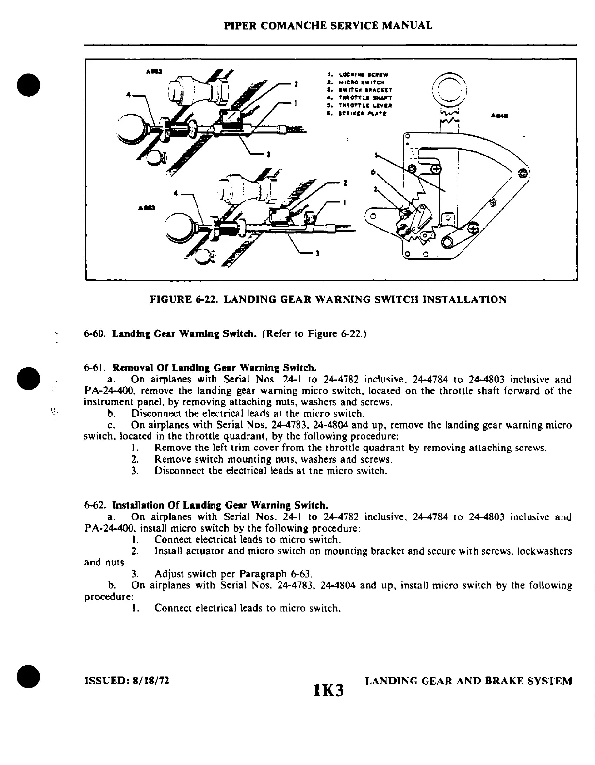
FIGURE
6-22.
LANDING
GEAR
WARNING
SWITCH
INSTALLATION
6-60. Landing Gear Warning Switch. (Refer to Figure 6-22.)
6-61. Removal
Of
Landing Gear Warning Switch.
a. On airplanes with Serial Nos.
24-1
to 24-4782 inclusive. 24-4784 to 24-4803 inclusive
and
PA-24-400. remove the landing gear warning micro switch. located
on
the throttle shaft forward of the
instrument panel.
by
removing attaching nuts. washers and screws.
b.
Disconnect the electrical leads at the micro switch.
c.
On airplanes with Serial Nos. 24-4783. 24-4804 and up. remove the landing gear warning micro
switch. located
in
the throttle quadrant. by the following procedure:
I.
Remove the left trim cover from the throttle quadrant
by
removing attaching screws.
2.
Remove switch mounting nuts. washers and screws.
3.
Disconnect the electrical leads
at
the micro switch.
6-62. Installation
Of
Landing Gear Warning Switch.
a. On airplanes with Serial Nos.
24-1
to 24-4782 inclusive. 24-4784 to 24-4803 inclusive and
PA-24-400. install micro switch
by
the following procedure:
I.
Connect electrical leads to micro switch.
2.
Install actuator and micro switch on mounting bracket and secure with screws. lockwashers
and nuts.
3.
Adjust switch per Paragraph 6-63.
b.
On airplanes with Serial Nos. 24-4783. 24-4804 and up. install micro switch
by
the following
procedure:
I.
Connect electrical leads to micro switch.
ISSUED:
8/18/72
lK3
LANDING GEAR AND BRAKE SYSTEM
 Loading...


