PIPER COMANCHE SERVICE MANUAL
should be disassembled only so far as is necessary
to make
repair
or
replacement
of
the defective
parts. As a precaution,
wear safety glasses when
disassembling the cranking motor. Following are
general instructions for disassembling a typical
Bendix
dri ve cranking motor:
a.
Remove
the
cover
band,
if
present,
and detach the field coil
leads
from the brush
holders.
b.
If
gear
reduction, remove the drive
housing, and reduction housing.
c. Remove the bolts attaching the drive
housing and commutator end frame to the field
frame assembly. Discard the tang lock washers.
d. Separate the commutator end
fratTI'
armature
assembly,
field
frame,
and
dri .
housing.
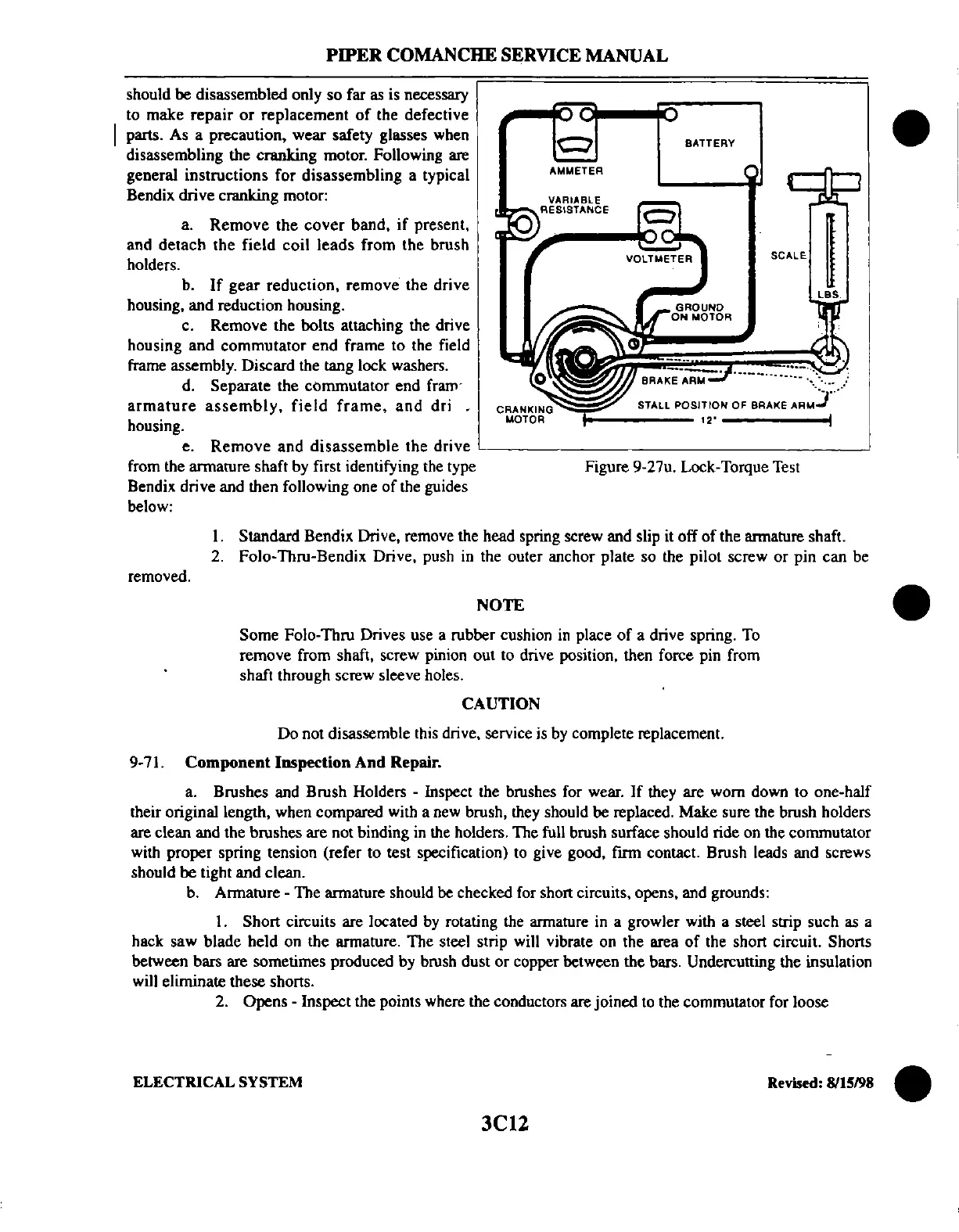
BATTERY
AMMETER
CRANKI~NG~~~~~S~TA~L~L~P:::OSITtON
OF
BRAKE
ARM)'
uOTOA'
12'
I
e.
Remove
and
disassemble
the drive
'----------------
___
---'
from the armature shaft by first identifying the type
Bendix drive and then following one
of
the guides
below:
Figure 9-27u. Lock-Torque Test
removed.
I. Standard Bendix Drive, remove the head spring screw and slip it off
of
the armature shaft.
2.
Folo-Thru-Bendix Drive, push
in
the outer anchor plate so the pilot screw
or
pin can be
NOTE
Some Folo-Thru Drives use a rubber cushion
in
place
of
a drive spring.
To
remove from shaft, screw pinion out to drive position, then force pin from
shaft through screw sleeve holes.
CAUTION
Do not disassemble this drive, service is by complete replacement.
9-71.
Component
Inspection
And
Repair.
a. Brushes and Brush Holders - Inspect the brushes for wear.
If
they are worn down to one-half
their original length, when compared with a new brush, they should be replaced. Make sure the brush holders
are clean and the brushes are not binding in the holders. The full brush surface should ride on the commutator
with proper spring tension (refer to test specification) to give good, firm contact. Brush leads and screws
should
be
tight and clean.
b. Armature - The armature should be checked for short circuits, opens, and grounds:
I.
Short circuits are located
by
rotating the armature in a growler with a steel strip such as a
hack saw blade held on the armature. The steel strip will vibrate on the area
of
the short circuit. Shorts
between bars are sometimes produced by brush dust
or
copper between the bars. Undercutting the insulation
will eliminate these shorts.
2.
Opens - Inspect the points where the conductors are joined
to
the commutator for loose
•
ELECTRICAL
SYSTEM
Revised:
8115198
•
3el2
 Loading...


