a·"
.7
PIPER
COMANCHE
SERVICE
MANUAL
A.1l2
4
3
I.
T_OW
.....
AI,y.
&.
,..
AD.AlIT"I..,.
le_._
l.
I,.I"IT
'WITCH
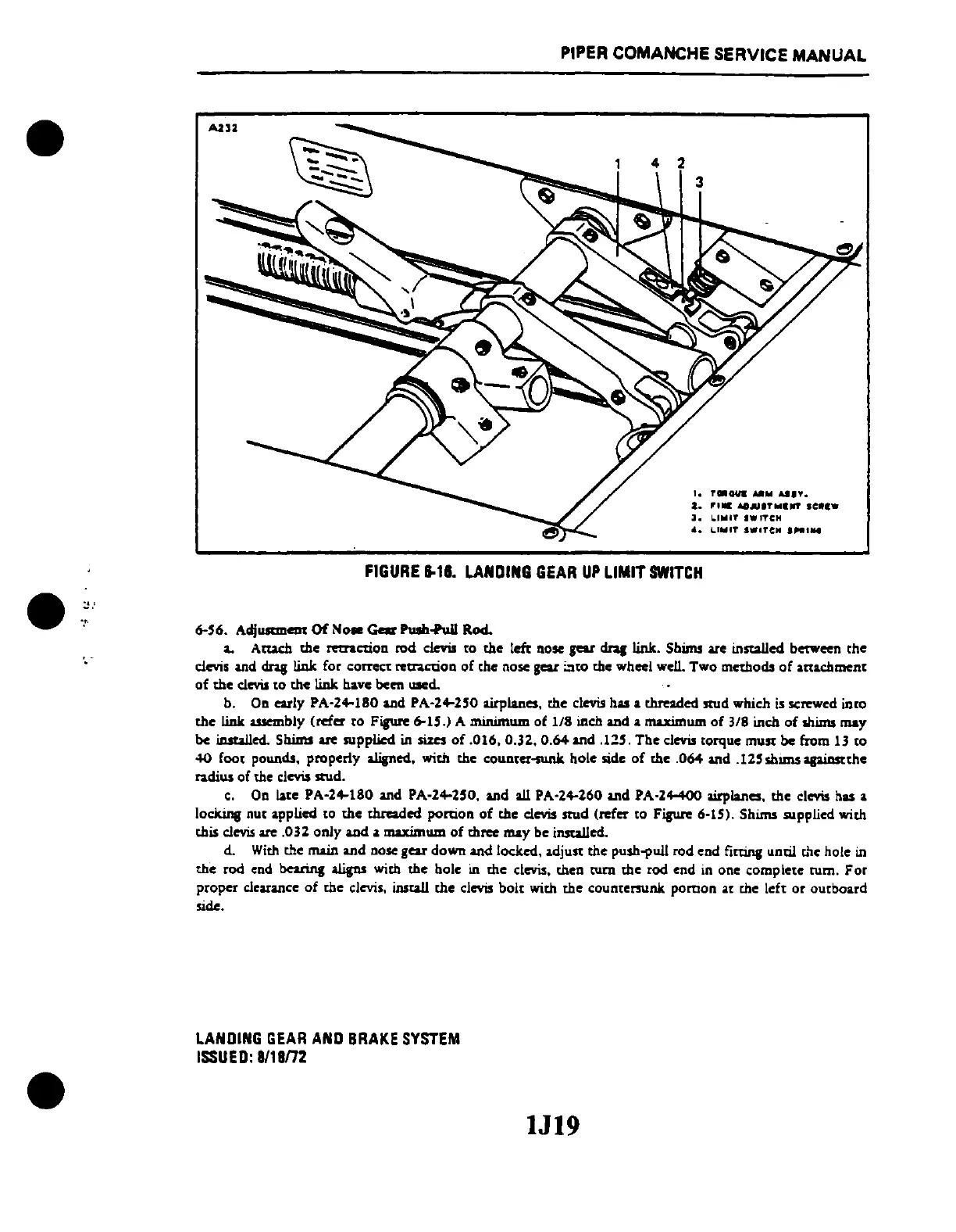
FIGURE
1-18.
LANDING
GEAR
UP
LIMIT
SWITCH
6-'6.
Adj
.......
em
Of
No.
Gar
Pulh1'ull Rod.
a.
Atw:h
the
m:raction
rod
clevis to
the
lcfr no
..
gear
dl2J
link. Shims are installed betWeen
the
clevis and
dl2J
link for
correct
retraction
of
the nose gear
~'tO
the wheel well.
Two
methods
of
attachment
of
the
clevis
to
the
link have been used.
b. On early PA·24-180 and PA-24-2'O airplanes,
the
clevis has a threaded stud which is screwed intO
the
link assembly (refer
to
Figure 6-15.) A minimum of
1/8
inch and a maximum
of
3/8
inch
of
shims
may
be installed. Shims are supplied in
sizes
of
.016, 0.32. 0.64 and
.Il'.
The
clevis torque
must
be from 13
to
40
foot pounds. properly
aliped.
with
the
counter-sunk hole side
of
the .064 and
.12'
shllllS
apiDstthe
radius of the clevis stud.
c.
On late PA-24-180 and PA-24-250. and all PA-24-260 and PA-24-400 airplanes.
the
clevis has a
locking nut applied to
the
threaded portion
of
the clevis
stud
(refer to Figure 6-15). Shims supplied with
this clevis are
.032
only
and a maximum
of
three
may
be installed.
d.
With
the main and nose gear down and locked. adjust
the
push1'uIl rod end fitting until the hole in
the
rod end
be2rins
aligns
with
the
hole in
the
clevis, then
tum
the
rod end in one
complete
rum.
For
proper
clearance
of
the
clevis, insta.ll
the
clevis
bolt
with
the
countemlnk
pomon
at die left
or
ourboard
side.
LANDING
GEAR
AND
BRAKE
SYSTEM
ISSUED:
8/18m
lJ19
 Loading...


