,
..
PIPER
COMANCHE
SERVICE
MANUAL
...
('~------
TIMING
MARK
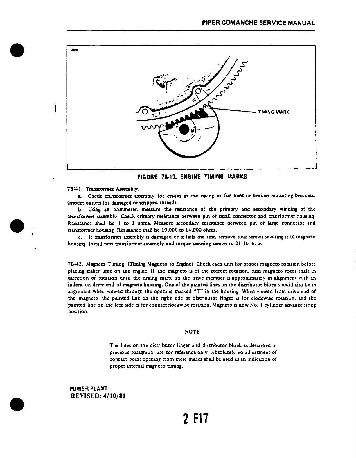
fiGURE
78·13.
ENGINE
TIMING
MARKS
7B41.
Traasformer
.u.mbly.
•.
Check transfor:net
....
mbly for cracks in the
casi",
or for bent
or
broken mounting bracket •.
Inspect
oudet.
for damaged or stripped threads.
b.
Using
an ohmmeter, measure the resistance
of
the primary and secondary winding of the
transformer assembly.
Check.
primary resistance between pin
of
small connector Uld tnnsfom1er
hou.sing
Resistance shall be 1
to
3 ohms. Measure secondary resistance betWeen
pm
of large connector and
transformer
"ouslng Resistance shall be 10,000 to
14,000
ohms.
c.
If
transformer
i1S5embly
IS
damaged
or
it fails
the
rcst, remove
four
screws securing it to magneto
housmg. Install new transformer assembly Uld torque securing screws to 25·30 lb.
In.
7B
.....
2.
Mqnno
Timing. (Timing
Mapeto
to Entdnc) Check each unit for proper
magneto
rotation
before
placUl! eIther unit
on
the engme.
If
the
magneto
is
of
the correct
rounon.
rum magneto rotor shaft m
direction
of
rotatlon
unell the timing marK on the drive
member
is
a.pproximately in alignment with an
indent
on
drive
end
of
magnno
housing.
One
of
the
pamted
lines
on
the
distributor
block should also be In
alignment when viewed through
the
opening
marked
'"T"
in
the
housing When
VIcwed
from drIve end
of
the
magneto,
the
painted
linc
on
the
right side
of
disaibutor
finger IS
for
clockwise
rotanon,
and
the
painted
line on
the
left side
15
for counterclockwise
rotation
..
\1.agncto
is
now
:-';0. 1 cylinder advance firing
posItion.
!'IOTE
The
lines on the
dinributor
finger
lnd
distributor
block
as
described in
prcvlous paragraph. are
for
reference only Absolutely no
adjuscnent
of
contact
point
opening itom these marks shall be used
lS
an indication
of
proper
internal magneto
tl1T1ing.
POWER
PLANT
REVISED: 4/10/81
2F17
 Loading...


