PIPER AIRCRAFT, INC.
PA-28-161, WARRIOR III
MAINTENANCE MANUAL
PAGE 16
Nov 30/06
5C22
74-10-00
(12) Distributor gear assembly
(a) Install carbon brush into spring.
1 Insert small end of carbon brush
tapered end of spring.
2 Turn carbon brush clockwise until
shoulder of carbon brush seats
spring.
(b) Install carbon brush assembly into
distributor gear.
1 Insert the open end of the spring
into open end of the distributor
gear shaft.
2 Gently press the carbon brush
and spring assembly into the shaft
until the spring seats on the
bottom of the shaft. The top of the
carbon brush should protrude
from the top of the shaft
approximately 1/4 inch.
(13) Install distributor block
(a) Assemble the distributor gear in the
distributor block with the L&R facing
you.
(b) Assemble the bearing bar to the
distributor block as shown in Figure 14.
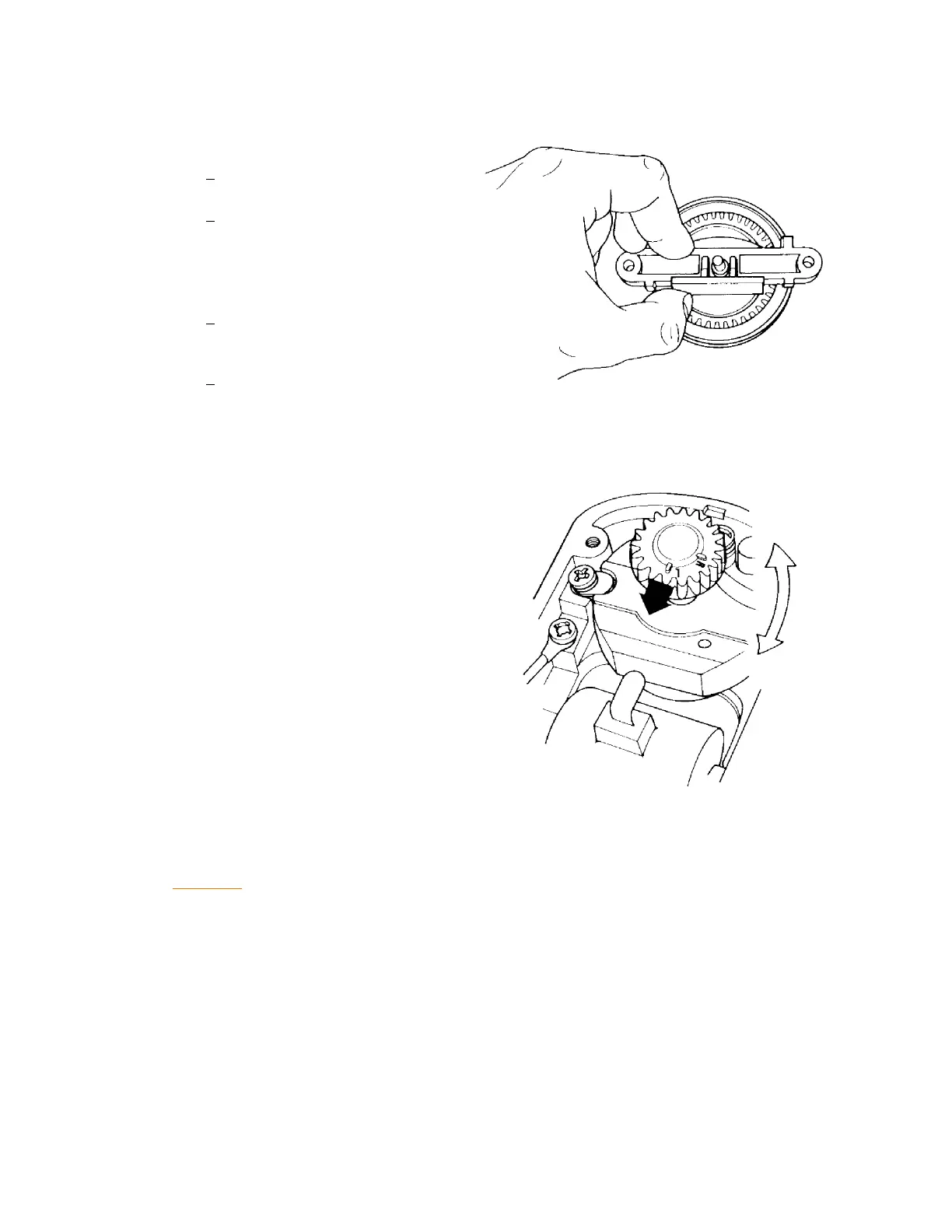
(14) Install rotor gear onto end of rotor shaft.
(15) Align the "L" or "R" (depending on the
rotation of the magneto—look at data plate)
on the rotor gear so that it points up, toward
the high tension lead of the coil. Secure
rotor shaft to prevent rotation during
assembly. Alignment of rotor gear is critical.
(See Figure 15.)
(16) Align the "L" or "R" hole in the distributor
gear with the "L" or "R" in the distributor
block. Use "L" for left-hand rotation and "R"
for right-hand rotation magnetos.
CAUTION: DO NOT ROTATE MAGNETO ROTOR SHAFT WITH THE T-118 TIMING PIN
INSERTED IN THE DISTRIBUTOR BLOCK. IF ROTOR SHAFT IS ROTATED
WITH TIMING PIN INSERTED, THE MAGNETO MUST BE DISASSEMBLED
AND INSPECTED FOR DISTRIBUTOR BLOCK AND GEAR DAMAGE.
(17) Lock the distributor gear in place with the T-118 timing pin through the appropriate hole in the
block and gear. Then:
(a) Place distributor block spacers on magneto frame.
(b) Place distributor block on magneto frame. The distributor gear and rotor gear are properly
meshed when the index mark on the rotor gear aligns with the index mark on the
distributor block.
(c) Secure distributor block to frame with screws provided.
Rotor Gear Alignment
Figure 15
Bearing Bar Assembly
Figure 14

 Loading...


