PIPER AIRCRAFT, INC.
PA-28-161, WARRIOR III
MAINTENANCE MANUAL
PAGE 15
Nov 30/06
5C21
74-10-00
(d) Insert T-150 "E" Gap Gauge between the pole laminations in the rotor shaft and the pole
laminations in the frame. Read the magneto data plate for magneto rotation.
1 For old style rotor (i.e. - no slots on the magnet head), insert flat end of T-150 "E"
Gap Gauge. Insert the "E" Gap Gauge against the right lamination for right-hand
rotation magnetos and against the left laminations for left-hand rotation magneto.
2 For new style rotors (with slots on magnet head), insert notched end of T-150 "E"
Gap Gauge. Locate the appropriate "L" or "R" timing slot on the rotor magnet head
and insert the notched end of the "E" gap gauge. Use the "L" slot for left-hand
rotation magnetos and the "R" slot for right-hand rotation magnetos.
(e) Rotate the magneto frame on the T-125 assembly fixture until the T-150 "E" Gap Gauge
rests against the pole lamination in the magneto frame. Rotate the magneto frame
clockwise for left-hand rotation magnetos and counterclockwise for right-hand rotation
magnetos. The magneto rotor shaft is now in "E" Gap position.
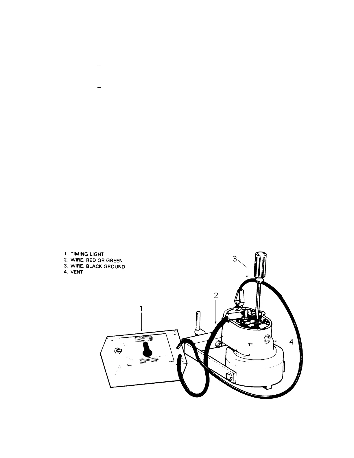
(f) Using a timing light (see Figure 13), adjust the contact points to be just opening when the
frame is against the T-150 gauge. This will provide a point gap opening of .008-.012
inches.
(g) Secure the points in this position by tightening the screws. Torque adjusting screw to
18-20 in.-lbs. Torque the pivot screw to 15-18 in.-lbs.
(h) Apply cam grease sparingly to each lobe of the cam.
(i) Attach coil lead wire to the vertical bronze male terminal of the primary point assembly.
(11) Assemble the condenser into the distributor housing, being sure to rotate the condenser wire
the same rotation as the condenser is tightened in the housing.
Magneto Internal Timing
Figure 13

 Loading...


