Chapter H - CEPHALOSTAT
H-28 ProMax X-ray unit with DImax3
ADJUSTMENTS AND CALIBRATIONS
Technical manual
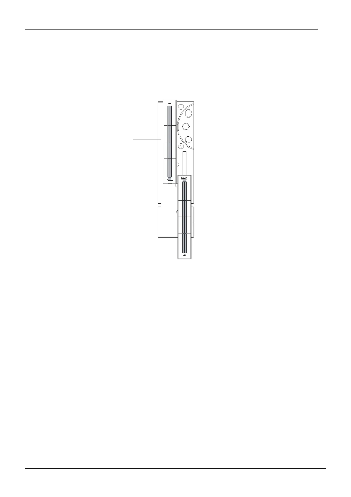
The beam image should reach but not overlap the lower edge of the rectangle marked on
the beam alignment tool, and the beam must appear within the left and right borders of
the rectangle as shown on the Fig. 49 below.
If it does not adjust the second primary slot position. Refer to section 1.13 “Adjusting the sec-
ond primary collimator position” on page H-29.
NOTE The upper limit of the beam may overlap the upper edge of the rectangle.
Figure 49
Move the beam alignment tool to the upper position on the sensor alignment tool as shown on
the figure above.
Stand behind the tube head and protect yourself from radiation. Press and hold down the
exposure button. The image of the radiation beam will appear on the alignment tool.
The beam image should appear within the borders of the rectangle marked on the beam
alignment tool as shown on the figure above. If it does not adjust the second primary slot posi-
tion. Refer to section 1.13 “Adjusting the second primary collimator position” on page H-29.
NOTE The lower limit of the beam may overlap the lower edge of the rectangle.
PXR_Adj_digiceph14.eps
Beam alignment
Beam alignment
tool in upper
position
tool in lower
position

 Loading...


