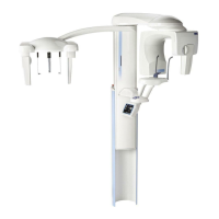
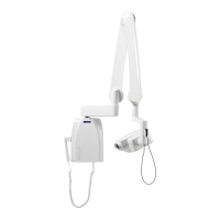
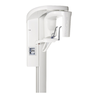
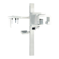
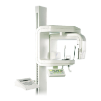
TOC - 4 ProMax X-ray unit with Dimax3
TABLE OF CONTENTS
Technical Manual
3 REPLACING THE GUI SOFTWARE........................................................... F-10
3.1 GUI software update, only for colour GUI ................................................. F-10
3.2 Replacing GUI software chip, only for black/white GUI............................. F-11
4 REPLACING PCBS.................................................................................. F-12
4.1 Patient position control PCB ..................................................................... F-12
4.2 Graphic user interface (GUI) PCB............................................................. F-13
Chapter G COLUMN
1 ADJUSTMENTS......................................................................................... G-1
1.1 Frankfort plane positioning light ................................................................. G-1
1.2 Adjusting the telescopic column position ................................................... G-3
1.3 Calibrating the column motor position sensor ............................................ G-5
2 REMOVING THE COVERS ....................................................................... G-9
2.1 Removing the telescopic column upper front panel ................................... G-9
2.2 Removing the telescopic column rear cover plates.................................. G-11
3 REPLACING THE COLUMN MOTOR...................................................... G-12
3.1 Replacing the motor................................................................................. G-12
3.2 Replacing the lift nut assembly ................................................................ G-19
4 REPLACING/UPGRADING SOFTWARE ................................................. G-26
4.1 Replacing the CPU PCB software chips (alternative 1) ........................... G-26
4.2 Loading the software from a computer (alternative 2).............................. G-28
5 REPLACING THE BATTERY ON THE RTC PCB ........................................ G-30
6 REPLACING PCBS................................................................................. G-31
6.1 Power PCB .............................................................................................. G-31
6.2 ETHERNET PCB and CPU PCB ............................................................. G-36
6.3 Input PCB................................................................................................. G-37
Chapter H CEPHALOSTAT
1 ADJUSTMENTS AND CALIBRATIONS .......................................................H-1
1.1 Required tools .............................................................................................H-1
1.2 Preparations before adjustments ................................................................H-3
1.3 Checking and adjusting the sensor head and second primary collimator
mutual position ............................................................................................H-3
1.4 Adjusting the sensor and second primary collimator rails ...........................H-5
1.5 Adjusting the sensor head connector and sensor head positions...............H-6
1.6 Adjusting the height of the cephalostat .....................................................H-10
1.7 Checking the cephalostat head support position ......................................H-13
 Loading...
