10 PARTS REPLACEMENT & REPAIR
68 Planmeca ProX Technical manual
25.Loosen four generator assembly frame attachment screws using a 2.5 mm Allen key. Lift
the generator assembly upwards. The generator assembly can now be lifted away from
the wall adapter. Disconnect the old Ethernet cable from its position and attach the new
Ethernet cable to the connector. Attach the assembly back to its position.
26.Remove the old arm cable from the Generator PCB.
27.Attach the ferrite to the new arm cable, to the middle of protective sleeve.
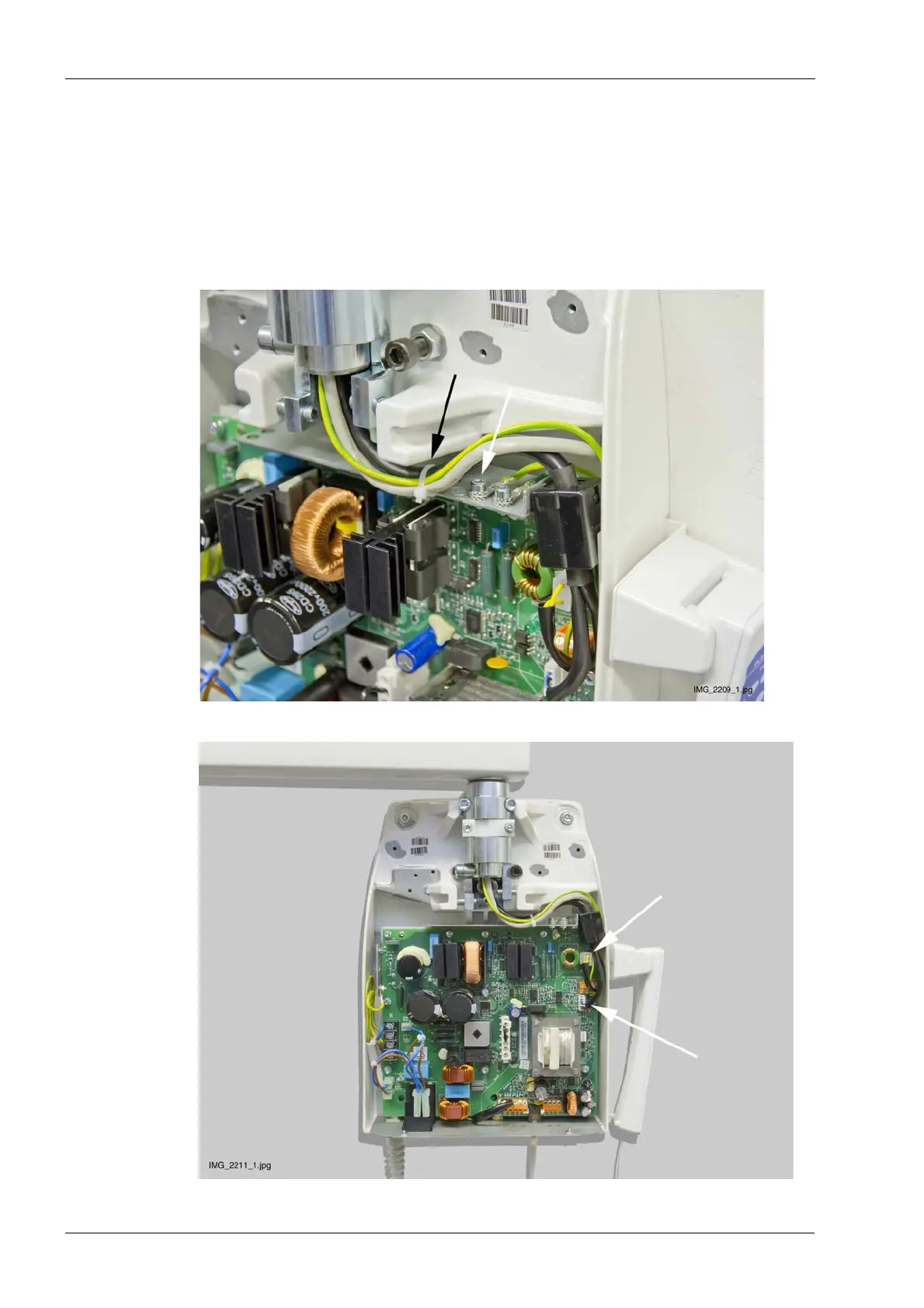
28.Attach the grounding lead to the frame using a 3 mm Allen key (white arrow).Secure the
cables with cable tie (black arrow).
29.Connect the cables,

 Loading...


